


The article is quite long, it is recommended to save it for reading.
Occasionally, I write articles in online forums and publish tutorials for DIY projects, and I often receive replies asking me: How are these beautiful circuit diagrams drawn?

Recently, some of my students have been busy preparing for various maker competitions, and of course, writing competition texts is a part of that. Many maker competitions now require circuit diagrams to be included in the competition text, so students often ask me to help draw circuit diagrams. Instead of just giving them fish, I decided to write a simple tutorial to teach everyone how to draw beautiful circuit diagrams.
First, let me clarify that the circuit diagrams mentioned here are not the professional circuit schematics or PCB drawings seen in the images below (which correspond to the circuit schematic and PCB drawing of Arduino Mega 2560), but are schematic diagrams of the components used in some maker projects.
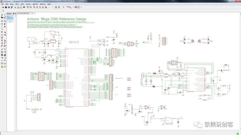
Arduino Mega 2560 Circuit Schematic
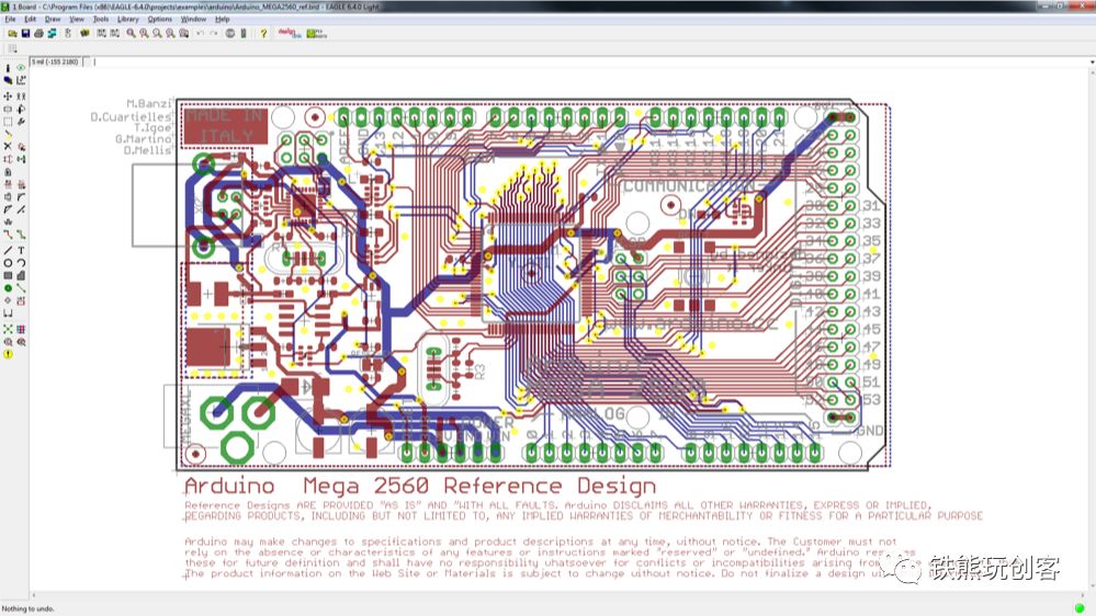
Arduino Mega 2560 PCB Drawing

# Software and Process Introduction
In fact, there is no unified software for drawing circuit diagrams; as long as you master the method, many tools can achieve similar effects as shown in the first image of this article. The numbers ① ② ③ ④ in that image were designed using different software, which are:
-
① Fritzing: Open-source and free circuit diagram drawing software, which was very popular in the maker community;
-
② Tinkercad Circuits: Free online circuit drawing, programming, and simulation software from Autodesk;
-
③ Microsoft PowerPoint (PPT) or Apple’s Keynote: These are design software for making slides;
-
④ Adobe Illustrator (AI): The famous high-definition vector image editor;
-
Inkscape: Open-source free high-definition vector image editor, similar to AI.
Yes, you read that right, the PPT we use daily is also on the list. Isn’t it an office software for making slides? How can it also be used to draw circuit diagrams? Let me tell you, PPT can not only be used to draw circuit diagrams, but it is also the easiest software for beginners to get started with, and I use it quite frequently in my daily drawing process. Why is that? Keep reading.
Additionally, these software have corresponding versions for both Windows and macOS platforms. Regardless of which software you use to draw circuit diagrams, some key steps are similar:
-
Circuit Analysis: Before drawing the circuit diagram, you should know what components are needed in the circuit diagram;
-
Finding Materials: Do you have to draw every component yourself? Of course not, most materials can be found online;
-
Material Processing: However, sometimes the materials found may not be satisfactory, so you can use PPT for simple processing;
-
Circuit Drawing: At this point, you will use some of the software mentioned earlier, and I will teach you some software skills in this section.
Next, I will introduce the general methods and skills for each step in chapters.

# Circuit Analysis
Circuit analysis should be the simplest step among the several steps; you should know which components you used in the entire project. Although this step is simple, it is also very important, as it will directly determine which software can be used later and may even affect the convenience of drawing the circuit diagram.
For example, if the components you used are just some basic and commonly used modules, you can directly use Fritzing or Tinkercad Circuits to draw; both of these software have many common electronic module materials in their built-in libraries. You can explore what materials are included; this article cannot cover everything, but there are quite a few.

# Prepare Materials
Preparing materials mainly refers to finding the electronic component images needed; here are a few common ways I use.
## In Fritzing to Find Materials
In the circuit analysis chapter, I mentioned that Fritzing software comes with many electronic component module materials, and the materials inside are all high-definition vector graphics that can be enlarged freely.
Fritzing is a very popular circuit diagram drawing software in the maker community; you can see many circuit diagrams drawn using this software online, but unfortunately, it seems that the last version update has been stuck at version 0.9.3b from June 2, 2016, and has not been updated for more than three years.
Download link: http://fritzing.org/download/
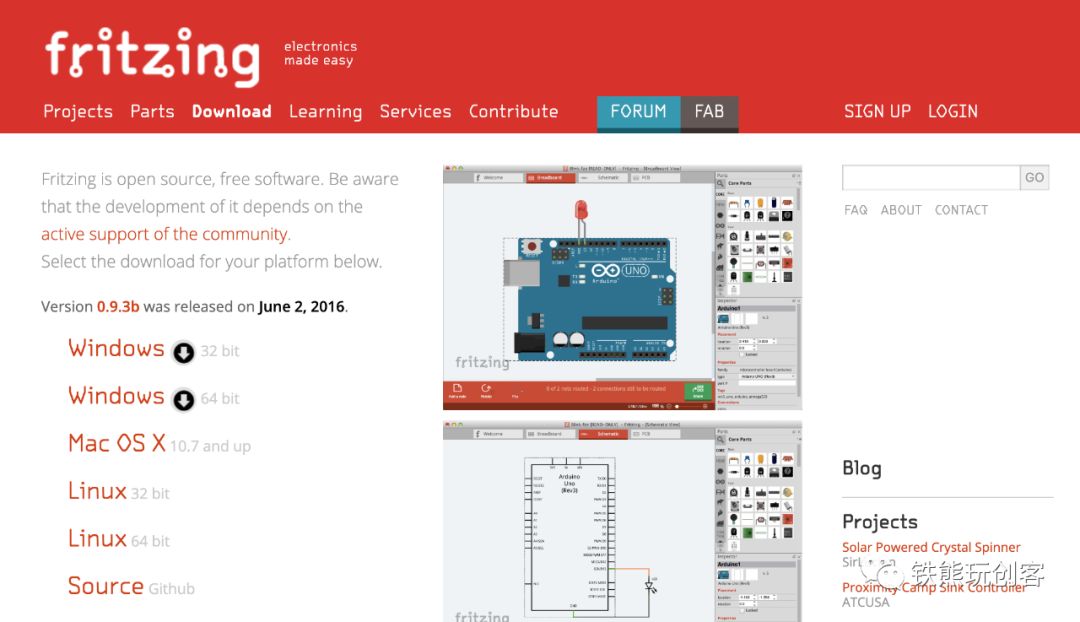
Fritzing
First, open the Fritzing software, then switch to the “Breadboard” tab, click the “magnifying glass” button on the right, and then enter the component you want to search for, for example, I searched for “Arduino Uno” here, and then press Enter, it will load the modules related to “Arduino Uno”. Find the module you want and drag it to the editing area as shown in the image below.
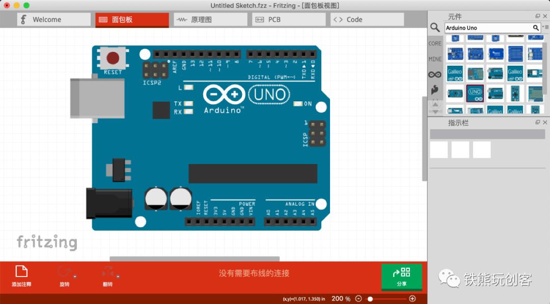
Searching for materials in Fritzing
If your entire circuit diagram is drawn using Fritzing, just continue to find other materials and connect them. If there are only some materials you want to draw in Fritzing, you will obviously need other software to assist in drawing. Therefore, you need to export the corresponding material drawings by clicking: File → Export → As Image → SVG, and you can export the material. Of course, you can also export in PNG or JPG format, depending on which software you will use for editing later.
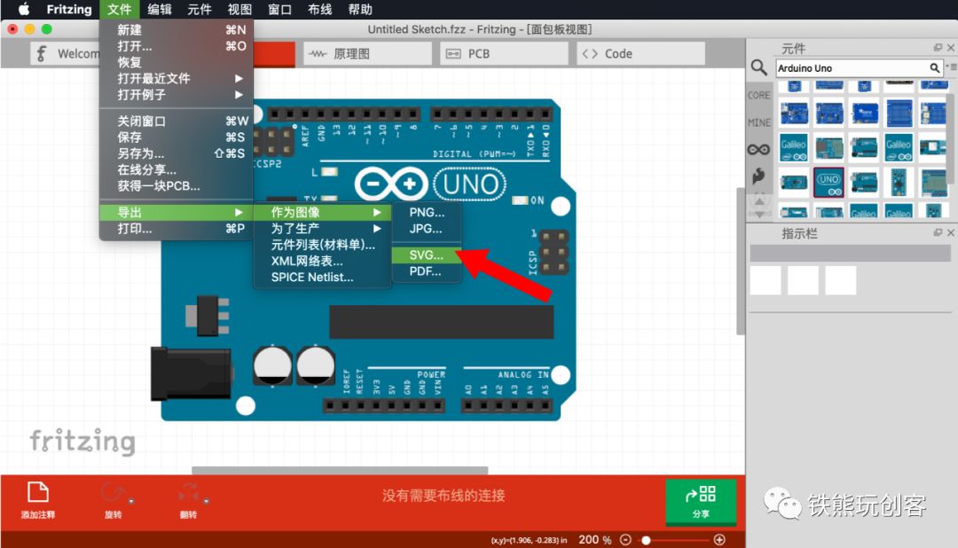
Exporting materials from Fritzing
If you want to edit using Adobe Illustrator or Inkscape, exporting in SVG format is the most suitable; if you want to edit using PPT, and if you have PPT 2019 or later, it is also recommended to export in SVG format because starting from PPT 2019, it directly supports opening vector graphics format, i.e., SVG format. If your PPT software is below this version, it is recommended to export in PNG format, as PNG format has a transparent background compared to JPG format, making it less likely to cause image overlap issues when drawing the circuit diagram.
## Finding Materials in Tinkercad
Tinkercad Circuits is a circuit drawing, programming, and simulation software launched by Autodesk for youth maker education. It is completely free software, but you need to register an account before using it. It supports simple circuit diagram drawing, Arduino graphical programming, and Arduino code programming. Even more impressive, it also supports circuit simulation! With the software’s updates, the circuit material library inside has become richer.
First, enter the Tinkercad website: https://www.tinkercad.com/, after logging in, go to your personal work page, select the “Circuits” tab from the left menu, and click the “Create new Circuit” button to enter the circuit diagram editing interface.
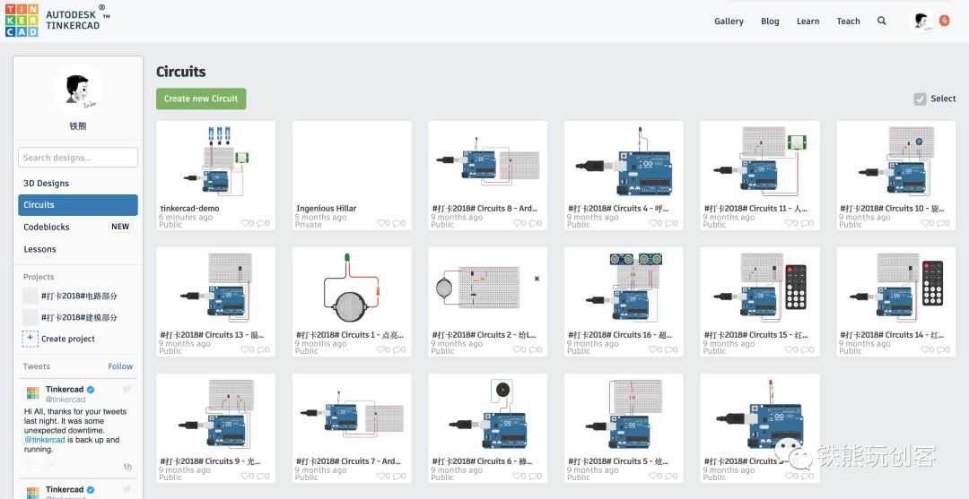
Tinkercad Dashboard
The circuit diagram editing interface has various electronic component modules on the right side. After finding the desired material, remember to enlarge it as much as possible, then take a screenshot to save it for later editing. Of course, just like in Fritzing, if you can find all the materials here, you can directly draw the wiring diagram here, which will be much more convenient.
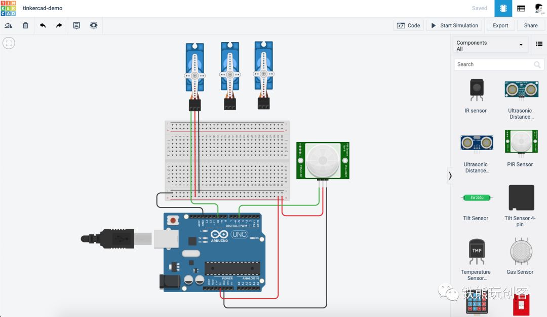
Tinkercad Circuits
Of course, Tinkercad Circuits can not only draw circuit diagrams but also directly write programs (both graphical and code supported) and even support simulation, making it a great option for teaching.

tinkercad-simulation
## Searching for Materials on the Internet
You can use Baidu or Google to search for corresponding electronic component drawings or photos; if you are lucky, you can directly find relatively clear images. It is important to note that you should try to find images without watermarks and taken from a top-down perspective, and the image size should also be as large as possible to achieve better results when drawing later. If you can find flat component drawings or even vector graphics drawn by others, that would be the best, but it is often difficult to find, so we can look for relatively clear and clean drawings and process them later.

Baidu search for electronic components

Google search for electronic components
Taobao: Taobao is also a huge image material library; you can directly search for corresponding components on Taobao or go to the store where you bought them to see if you can find watermark-free photos or screenshots.

Taobao search for electronic components
For example, the detail image from the store below meets several conditions: it is taken from a top-down perspective, has no watermark, and the lines drawn around the module boundaries are clear, allowing you to save it by screenshotting. This image will be used as an example to explain how to process materials using PPT.
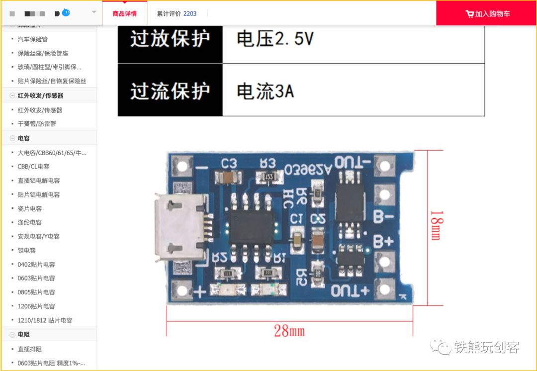
Taobao store electronic component detail page
## Finding Materials in Manufacturer’s Galleries
After so much useless talk, if you haven’t clicked to close the page, it means you are a true fan, so here comes a big killer!
In fact, many large manufacturers have their own component drawing libraries; some manufacturers provide high-definition component vector graphics for download, while others may not provide vector graphics for download, but generally, you can download high-definition drawings. Where can these drawings usually be found? Generally, there will be a link to the product wiki on the product page of their official website, which means most products will have a usage tutorial, and usually, there will be related drawings on their tutorial page.
Since I often use electronic components from DFRobot, whose product quality is good (remember to pay me for advertising~), I will take them as an example. Enter their official website, select the product you want, and then click the “Product Wiki” link at the bottom of the product page. For example, for DFRobot’s latest control expansion board, you can see a high-definition drawing in the upper right corner of its wiki page; try searching for it yourself.
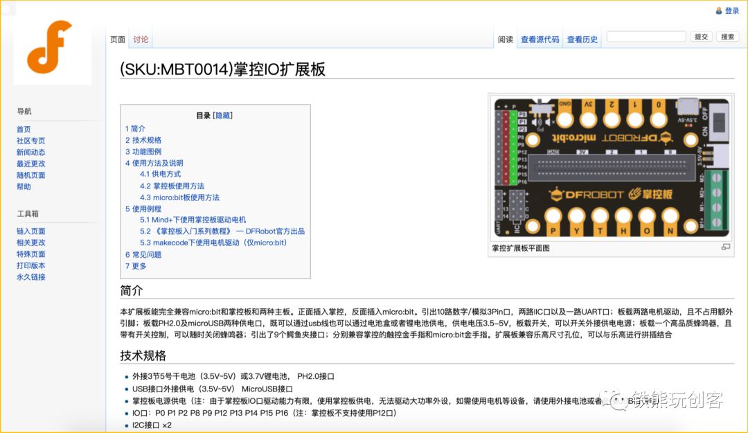
Control Board wiki page
Of course, DFRobot also has a component drawing repo on GitHub where you can download it directly. The direct link is: https://github.com/DF-Jane/DFRobot-SVGs. This repo basically includes high-definition drawings of DFRobot’s commonly used products, but the downside is that this repo seems to have not been updated for a long time, and their latest product drawings are basically not available. I hope they can continue to update it in the future. Of course, since I am quite familiar with some friends at DFRobot, I have some special channels to obtain their latest drawings, haha.
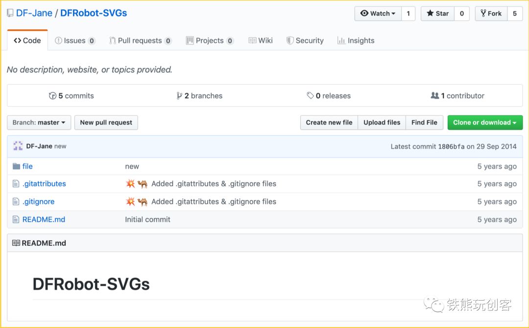
DFRobot SVG drawing repo
In addition to DFRobot’s drawings, I also have some drawings from other manufacturers. To make it easier for everyone, I will package these drawings and upload them online for download later. You can reply “component drawings” in the background of my public account “Iron Bear Plays Maker” to automatically receive the download link.
Here, I would like to mention to all manufacturers: if you have organized high-definition drawings, please send me the download link, and I will compile and share them with everyone.

# Material Processing
After writing 3000 words, we finally reached the material processing chapter… It feels like finishing this is a long way off… Let’s start the tofu project mode, haha.
The material processing here does not refer to professional software like PS, but rather using PPT for simple processing! Yes, using PPT for processing! Open the PPT software, I hope you are using PPT 2013 or later; if not, please turn left and download a higher version of PPT. Import the images to be processed into PPT, then go to the “Picture Format” editing tab. If you don’t see this tab, double-click the image. Then click the “Remove Background” button pointed out by the arrow, and the image will enter the background removal editing mode.
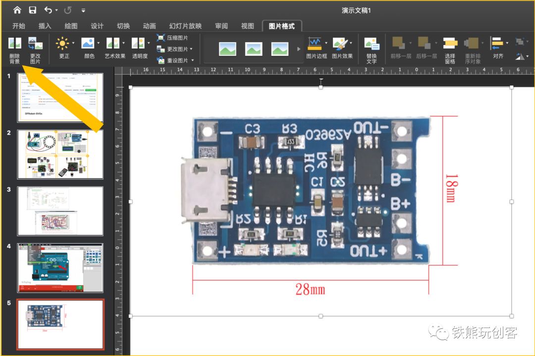
PPT Picture Format Page
In the background removal editing mode, adjust the boundaries appropriately and mark the areas to delete or retain; the red area is the background area to be deleted. After some simple adjustments, you can get an image with a transparent background, which you can right-click to save to your computer, or you can directly draw the circuit connection diagram in PPT. You can see that all the image materials in this article were processed in PPT.
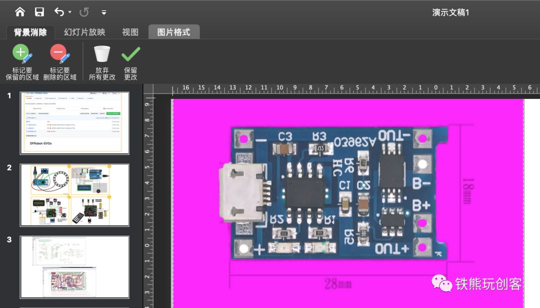
PPT Remove Image Background
Of course, I used the PPT software on Mac, which is quite similar to the one on Windows, with just slight differences in the interface. To give you a more intuitive understanding of this process, I specially found a GIF showing how to remove backgrounds using PPT on Windows; feel free to experience it. PPT is actually a great tool for background removal.

PPT Background Removal Dynamic Demonstration

# Circuit Drawing (Software Skills)
Finally, we have reached the stage of how to draw circuit diagrams. You might think this is the key point of the article, but after the steps above, the rest is quite simple. Below, I will briefly introduce how to use different software.
## Drawing Circuit Diagrams in Fritzing
Drawing in Fritzing is very simple! You just need to find the components you want and drag them out, then connect them one by one. Because this software is really easy to operate, I won’t elaborate further; I’ll take a shortcut and directly provide a tutorial link:
-
How to draw circuits using Fritzing software:http://cnlearn.linksprite.com/?p=185#.XRDSwm8zZ0s
## Drawing Circuit Diagrams in Tinkercad
How to draw in Tinkercad Circuits? I won’t elaborate further; I’ll open a little portal for you:
-
[Teacher Yu’s Public Welfare Course Summary] Tinkercad 3D Modeling + Circuits Electronic Circuit: https://mp.weixin.qq.com/s/TCzL7UKAGOeV0nO0db1xDA
This is a series of public welfare micro-classes conducted by Teacher Yu from Hangzhou Victory Experimental School during the summer of 2018. You can learn about Tinkercad Circuits drawing skills as well as Arduino programming knowledge and 3D printing modeling knowledge from the website above. It is a very good learning resource, so make sure to check it out when you have time!
## Drawing Circuit Diagrams in PPT
Many people may not have heard of the first two software, but everyone should know PPT, right? If you don’t know this, I really can’t understand how you have persisted to read this far, after all, you’ve already read over 4000 words.
Drawing circuit wiring diagrams in PPT is simply about layout. I believe everyone has been making PPTs for many years. After finding and processing the materials according to the previous steps, place them all on the same page in PPT, adjust the size and position of the components according to the circuit relationship, and then insert lines, using some alignment operations for basic layout. Don’t know how to insert lines in PPT? Well, in PPT, click: Insert → Shapes → Lines, then adjust the line’s length, color, and position!
Here’s a little tip: while adjusting the line’s length with the mouse, hold down the