1
Hello today!
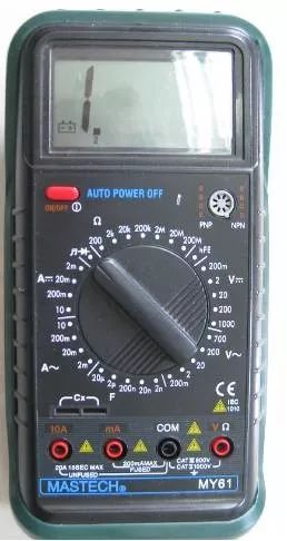
The digital multimeter can measure DC and AC voltage, DC and AC current, resistance, capacitance, frequency, batteries, diodes, etc. The overall circuit design is centered around a large-scale integrated circuit dual-slope A/D converter, equipped with a complete overload protection circuit, making it a superior performance tool and one of the essential tools for electricians.
 Precautions Before Operation
(1) Set the ON-OFF switch to the ON position, check the 9V battery. If the battery voltage is insufficient,

or “BAT” will be displayed on the display; at this point, the battery should be replaced; if it does not appear, proceed with the following steps;
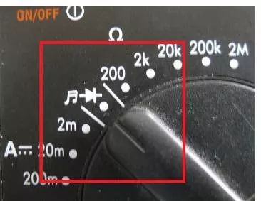
(2) Before testing, the function switch should be placed on the required range, and pay attention to the position of the pointer, as shown in the figure below;
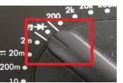
(3) It is particularly important to note that during measurement, if you need to switch gears or change probe positions, you must remove both probes from the measured object before switching gears and changing probe positions.
 Using and Precautions for Voltage Range
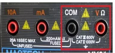
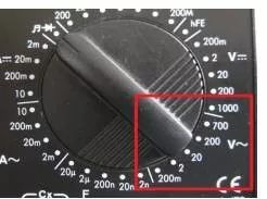
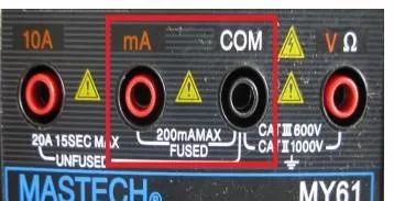
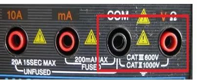
When measuring voltage, the black probe must be inserted into the COM hole, and the red probe into the V hole, as shown in the red box in the figure below;
If measuring DC voltage, turn the pointer to the indicated DC range in the figure below
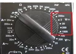
If measuring AC voltage, turn the pointer to the indicated AC voltage range in the figure below
(1) If you do not know the voltage range to be measured, set the function switch to the highest range and gradually decrease the range (do not change the range during measurement).
(2) If “1” is displayed, it indicates an overload range, and the function switch should be set to a higher range.
(3) △! indicates that do not input voltage higher than what the multimeter requires; a higher voltage value may be displayed, but there is a risk of damaging internal circuits.
(4) When measuring high voltage, special care should be taken to avoid electric shock.
(5) The internal resistance of the digital meter’s voltage range is very high, at least in the mega-ohm level, which has little impact on the measured circuit. However, the extremely high output impedance makes it susceptible to induced voltage, and data measured in some environments with strong electromagnetic interference may be false. Care should be taken to avoid external magnetic field interference on the multimeter (for example, when large power-consuming devices are in use).
(6) During the use of the multimeter, do not touch the metal part of the probes with your hands; this can ensure measurement accuracy and also ensure personal safety.
 Measuring and Precautions for Capacitance Range
Method for measuring capacitance capacity
As shown in the box in the figure below, turn the pointer to the capacitance range (F range)
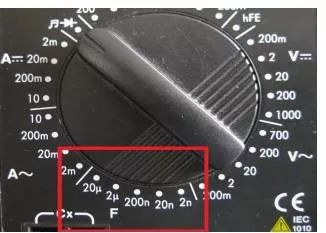
There are two holes on the lower left of the digital multimeter’s range, marked Cx, insert the capacitor to be measured into it for measurement; if there is a polarized capacitor, pay attention to the positive and negative poles.
Capacitance (or capacitance, Capacitance) refers to the amount of charge stored at a given potential difference; denoted as C, with the international unit being Farad (F), representing the physical quantity that characterizes the ability of a capacitor to hold charge.
1 Farad (F) = 1000 milliFarads (mF) = 1000000 microFarads (μF)
1 microFarad (μF) = 1000 nanoFarads (nF) = 1000000 picoFarads (pF)
How to Determine the Quality of a Capacitor?
Use an analog multimeter in the ohm range (adjust the range according to the capacitance) to first discharge the capacitor, then touch the capacitor’s two leads with the probes; at this time, the pointer will swing quickly and then return to the starting position. If the pointer swings but does not return to the original position, the capacitor is leaking (a slight leakage of large-capacity electrolytic capacitors is normal). If the pointer does not move, the capacitor is open (for very small capacitance such as a few pF, it may not be measurable; I can measure small capacitors like 3N3, 4N7 with the 10K range).
Method for Checking Capacitor Leakage
For capacitors above 1000 microFarads, quickly charge them using the R×10Ω range and initially estimate the capacitance, then switch to the R×1kΩ range and continue measuring; at this time, the pointer should not return but should stop at or very close to ∞; otherwise, it indicates leakage. For some timing or oscillation capacitors below several tens of microFarads (such as oscillation capacitors in color TV switch power supplies), the leakage characteristics are very high; any leakage renders them unusable. In this case, charge with the R×1kΩ range and then switch to the R×10kΩ range for continued measurement; similarly, the pointer should stop at ∞ and not return.
 Using and Precautions for Current Range
As shown in the box in the figure below, the multimeter current range is divided into AC and DC ranges. When measuring current, the multimeter pointer must be set to the corresponding range to perform the measurement.
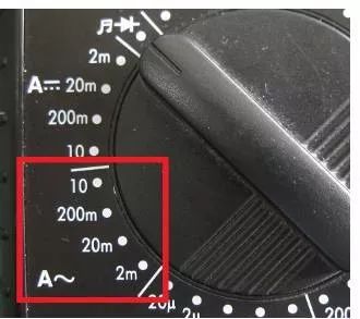
AC Range
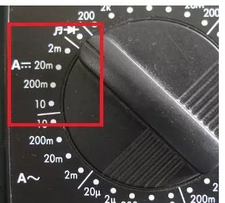
DC Range
When measuring current, if using the mA range, the black probe must be inserted into the COM hole, and the red probe into the mA range, as shown in the box in the figure below;
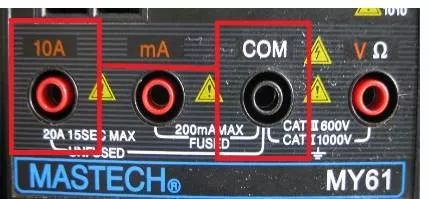
If using the 10A range for measurement, the black probe remains unchanged, still inserted into the COM hole, while the red probe is pulled out and inserted into the 10A hole, as shown in the box in the figure below.
Precautions for Current Measurement
(1) If you do not know the current range to be measured before use, set the function switch to the maximum range and gradually lower the range (do not change the range during measurement).
(2) If the display shows only “1”, it indicates an overload range, and the function switch should be set to a higher range.
(3) The probe socket indicates a maximum input current of 10A; measuring excessive current will burn the fuse.
 Using and Precautions for Diode Range
Set the multimeter pointer to the diode range as shown in the box in the figure below, insert the black probe into the COM hole, and the red probe into the V hole. This range can measure diodes, as well as transistors, encoder switches, and whether the circuit is connected.

Below is an example using a transistor and potentiometer
Transistor Measurement Method
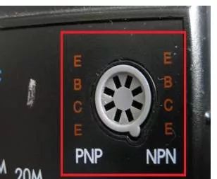
The basic structure of a transistor consists of two reverse-connected PN junctions, which can also be simply viewed as two connected diodes, as shown in the figure below, with PNP and NPN combinations.
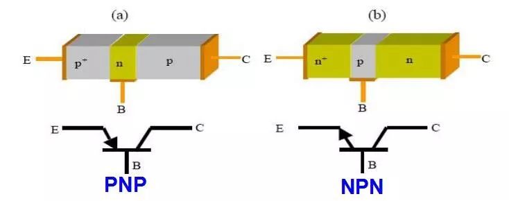
The three leads are called emitter (E), base (B), and collector (C) in order.
Transistor Measurement Method
Set the multimeter to the diode range. This range shows the voltage drop across the diode being measured. To determine the type and polarity of the transistor, connect the probes to any two leads of the transistor; if the reading is around 700 (in millivolts), it indicates a silicon transistor. If the displayed value is around 200, it is a germanium transistor. If there is no display (open circuit state shows 1), the red and black probes need to be swapped for testing. Additionally, the transistor type can be determined: if the red probe connects to one lead (base), and the other two leads connect to the black probe, both will conduct (showing a value), indicating it is an NPN transistor. If the black probe connects to one lead (base), and the other two leads connect to the red probe, both will conduct (showing a value), indicating it is a PNP transistor. Determining the emitter and collector requires other methods.
At the same time, using the resistance range, based on the transistor’s amplification factor and internal resistance, it can also be determined whether the transistor is NPN or PNP.
Determining the Quality of a Transistor
Connect the probes to any two leads of the transistor; if there is no display (open circuit state shows 1) or the buzzer sounds, swap the red and black probes for testing, and if the result is the same, the transistor is determined to be faulty.

Using and Precautions for Resistance Range
Set the multimeter pointer to the resistance range as shown in the box in the figure below, insert the black probe into the COM hole, and the red probe into the V hole, then measure the resistance value to be tested.
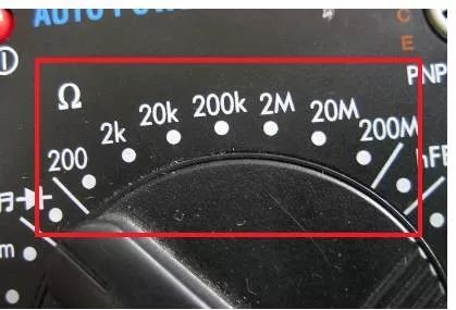
Precautions for Resistance Measurement
(1) If the measured resistance value exceeds the maximum value of the selected range, “1” will be displayed, and a higher range should be selected. For resistance greater than 1 MΩ or higher, it may take a few seconds for the reading to stabilize; this is normal for high resistance readings.
(2) When there is no input, such as in an open circuit situation, it will display “1”.
(3) When checking the internal circuit resistance, ensure that all power to the measured circuit is turned off and all capacitors are discharged.
(4) When shorting 200MΩ, about four digits will appear; during measurement, this should be subtracted from the reading; for example, if measuring a 100MΩ resistor, if it displays 101.0, the fourth digit should be subtracted.
(5) The resistance range can be used to roughly detect the quality of a capacitor; connect the red probe to the positive lead of the capacitor and the black probe to the negative lead. The multimeter’s reference power will charge the capacitor through the reference resistor; during normal operation, the voltage displayed on the multimeter will start from a low value and gradually increase until it overflows. If it displays overflow “1” immediately upon charging, the capacitor is open; if it continues to show a fixed resistance value or “000”, the capacitor is leaking or short-circuited.
(6) When checking the circuit continuity, the function switch should be set to the ” ” range, not the resistance range. During measurement, if no beep is heard, it can be determined that the circuit is not connected.
(7) When measuring small resistance values, first short the two probes to read the self-resistance of the probe leads (generally 0.2 to 0.3 ohms) to correct the measured value.
(8) The resistance range has over-voltage protection; mistakenly measuring voltage within the specified range will not cause damage. For example, the DT-830 digital multimeter’s resistance range allows a maximum input voltage (DC or AC peak) of 250 volts, which is the safety value for mistakenly using the resistance range to measure voltage, but it should not be used to measure resistance with power (such as from a battery or human body), as this may reduce the accuracy of the multimeter’s resistance and even damage it.
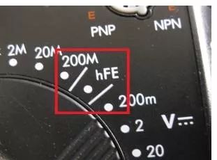
 Using and Precautions for hFE Range
This range is mainly used to measure the amplification factor β of the transistor. Before measuring, it is necessary to determine whether the transistor is PNP or NPN type, and to confirm the polarity of each lead.
Other Precautions for Using Multimeters
(1) During the use of the multimeter, do not touch the metal parts of the probes with your hands; this can ensure measurement accuracy and also ensure personal safety.
(2) When measuring a certain quantity, do not switch ranges while measuring, especially when measuring high voltage or large current; this should be especially noted. Otherwise, it may damage the multimeter. If a range switch is needed, the probes should be disconnected first, then switch the range and proceed with the measurement.
Maintenance Precautions for Digital Multimeters
The digital multimeter is a precision electronic instrument; do not change the circuit arbitrarily, and pay attention to the following points:
① Do not use beyond the rated range.
② Do not use the multimeter when the battery is not properly installed or the back cover is not tightened.
③ Only replace the battery and fuse after the test probes have been removed from the multimeter and the power has been turned off. Battery replacement: pay attention to the usage of the 9V battery; if replacement is needed, open the back cover screw, and replace it with the same model battery. When replacing the fuse, use the same model fuse.
④ After using the multimeter, set the switch to the “OFF” position. If not used for a long time, also remove the internal battery to prevent battery corrosion of other components inside the multimeter.

We are a maintenance-focused and life-loving team in Guangzhou.

Guangzhou YiGu focuses on medical equipment maintenance
Monitoring | Defibrillation | Blood Oximeter | ECG Machine | Ultrasound | Power System
Free Technical Consultation: 13760748227


WeChat ID: yigumed Long press the left QR code to follow
Copyright Statement|Content from the internet
This issue editor| Xiao 6zi
Submission Hotline| QQ 2595722347