Troubleshooting Inverter Circuit Boards
Generally speaking, the printed circuit boards on an inverter mainly include the drive board, main control board, and display board. The factors affecting the lifespan of the inverter’s printed circuit boards include the lifespan characteristics of the smoothing capacitors in the power supply section and the buffer capacitors in the IPM circuit board. The ripple current passing through the smoothing and buffer capacitors is constant and is minimally affected by the load on the main circuit, so their lifespan is primarily determined by temperature and the duration of power-on time. Unlike the main circuit, it is relatively difficult to assess the performance degradation of capacitors because they are soldered onto the printed circuit board; thus, it is generally estimated whether they are nearing their lifespan based on environmental temperature and usage time, prompting the replacement of the board.
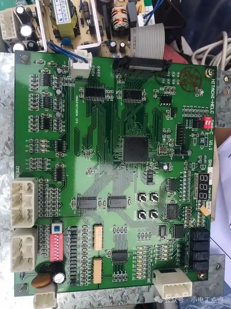
The logic control circuit board is the core of the inverter, concentrating large-scale integrated circuits and memory chips such as the central microprocessor, high-speed data processor, ROM, RAM, and EEPROM. It employs SMT (Surface Mount Technology), providing high reliability. The probability of failure in the board itself is extremely low; issues typically arise from incorrect operations, such as closing all control terminals simultaneously when powering on, which may trigger EEPROM fault information. In this case, simply resetting the EEPROM can eliminate the fault. It is important to note that because the distance between the pins of integrated chips is very small, care must be taken to prevent metal debris from falling in. Additionally, in environments with high dust or humidity, dust removal is essential.
The power supply circuit board provides the logic control power for the inverter, power for control terminals, power for the IPM drive, power for the surface operation display board, and power for the fan. These power supplies are derived from the main circuit’s DC voltage, processed through a switching power supply, and then output via transformers and rectifiers. Therefore, when a power supply circuit shorts, it can damage the rectifier circuit of that line and potentially affect other power supplies. For instance, if the control terminal’s 24V power supply is mistakenly shorted to ground, it can damage the transformer or switching power supply section on the power supply circuit board; a short in the fan power supply may cause other power supplies to lose power. Typically, such faults can be easily identified by visually inspecting the power supply circuit board.
The IPM circuit board includes drive and buffer circuits, as well as protection circuits for overvoltage and phase loss. Since the PWM signals from the logic control circuit board enter the IPM module through an optocoupler, during static testing, the optocoupler on the IPM circuit board should also be measured to determine if the IPM circuit board is functioning correctly.
After excluding faults in the main circuit components, if the inverter still does not operate normally, a simple and effective method is to remove the printed circuit board and check for any visible discoloration or localized burning on both sides. Based on the characteristics of the inverter’s failure, the faulty circuit board can be identified using a substitution method. For simple circuits like the absorption board, GE board, and fan power supply board, a multimeter can quickly identify faults.
If a circuit diagram is available, the voltages of each power supply on the circuit board can be checked according to the diagram, and waveforms can be observed using an oscilloscope, following a sequence from the back stage to the front stage. If no circuit diagram is available, a comparative method can be used to compare circuits with similar functions in the circuit diagram.
The causes of circuit board damage include the following:
[1] Poor quality of components, especially for high-power components, which have a higher probability of failure.
[2] Components damaged due to overheating or overvoltage, broken transformer wires, dried or leaking electrolytic capacitors, and resistors changing value due to prolonged exposure to high temperatures.
[3] Corrosion breakdown and insulation leakage of printed circuit boards caused by environmental temperature, humidity, water vapor, and dust.
[4] Damage to components and printed lines on the drive printed circuit board due to module failure.
[5] Poor contact of connectors, interference with microprocessors and memory, and failure of crystal oscillators.
[6] Original programs being disrupted by user adjustments, leading to non-functionality.
The operation and display panel includes parameter setting and display interface circuits, as well as light-emitting diodes or liquid crystal displays. The IC chips and auxiliary circuits within the display interface circuit generally do not fail easily; only when the LEDs dim or the display shows defects, or the LCD display noticeably fades should a new operation and display panel be replaced. These faults generally do not critically affect the operation of the entire inverter.
Printed circuit boards are coated with protective lacquer and other coatings; during testing, care must be taken to use a pointed probe to contact the metal being tested to avoid misjudgment. Since overheating and overvoltage can easily damage components, the switching power supply’s switching tube, switching transformer, overvoltage absorption components, power devices, pulse transformers, optocouplers for high voltage isolation, overvoltage absorption or buffer absorption boards and their components, charging resistors, field-effect transistors or IGBTs, voltage regulators or voltage regulator integrated circuits should be checked first.
When replacing printed circuit boards, there may also be issues with different versions. When confirming the need to replace a circuit board, check whether the board number and identification number are consistent; if they are not, technical guidance from the manufacturer is necessary. If the microprocessor numbers differ, the internal programs will also differ, which may result in variations in certain functions during use. Therefore, if program issues are confirmed during use, the manufacturer should be consulted.
After repairing the circuit board, it should be powered on for testing; at this time, do not directly power the inverter’s main circuit but use an auxiliary power supply to power the circuit board, checking each voltage with a multimeter and observing waveforms with an oscilloscope. Only after confirming everything is correct should it be connected to the main circuit for debugging.