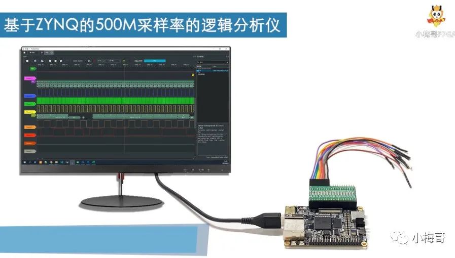
This article explains the process of creating an 8-channel high-performance logic analyzer. In this manual, we guide you to program the dedicated firmware we provide, allowing you to upgrade your BX71 core board into a high-performance logic analyzer with 500M sampling capability and 8 sampling channels, each with a storage depth of 400M.
Make sure you have installed the Vivado development software on your computer.
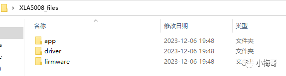
Download the XLA5008_files folder from the BX71 materials. There are three folders included.
-
app: The optimized PulseView logic analyzer software running on the computer.
-
driver: The driver installation tool for the computer logic analyzer.
-
firmware: The firmware program for the BX71 core board to implement the XLA5008 logic analyzer, including versions 7010 and 7020.
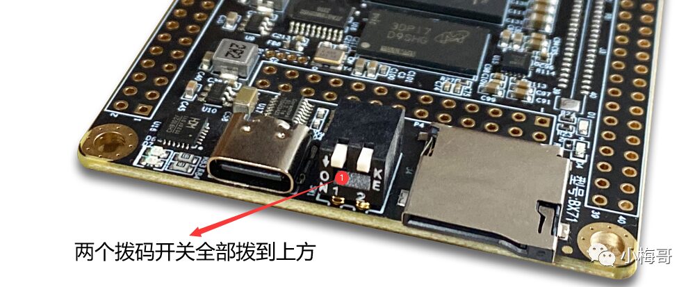
Set all the startup DIP switches on the BX71 development board to the upper position, which means using the JTAG boot mode.
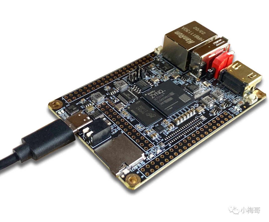
Connect the computer and BX71 core board using a USB data cable to the Type-C USB interface.
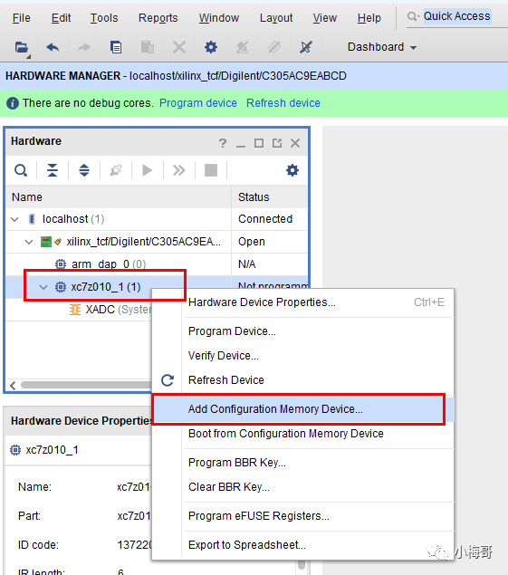
In the Vivado Hardware Manager, JTAG and ZYNQ devices will be detected. Depending on your device model, it may display as xc7z010 or xc7z020.
Select the ZYNQ chip, right-click, and choose the “Add Configuration Memory Device…” option.
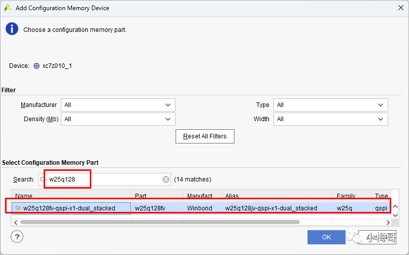
In the Search window, enter the Flash model used on the BX71 core board, which is W25Q128, and select the first result. Then click OK.
Once added, a prompt will appear asking if you want to program this configuration memory. Click OK to enter the file selection interface.
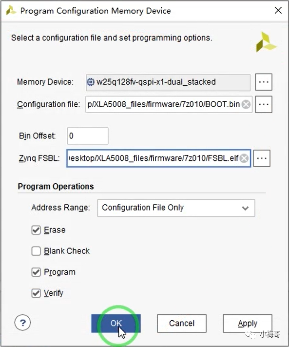
In the file selection interface, under the Configuration file option, select the BOOT.bin file of the logic analyzer firmware we provided. In the Zynq FSBL interface, select the FSBL.elf file we provided.
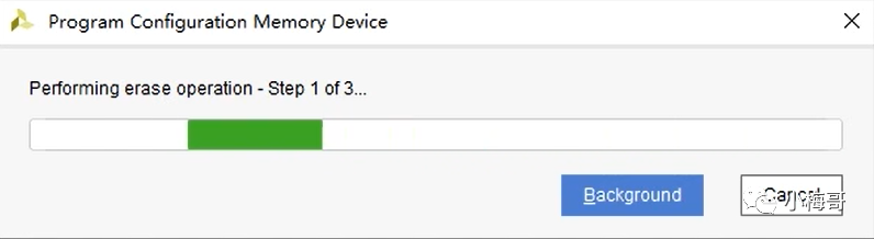
Click OK to start the download.
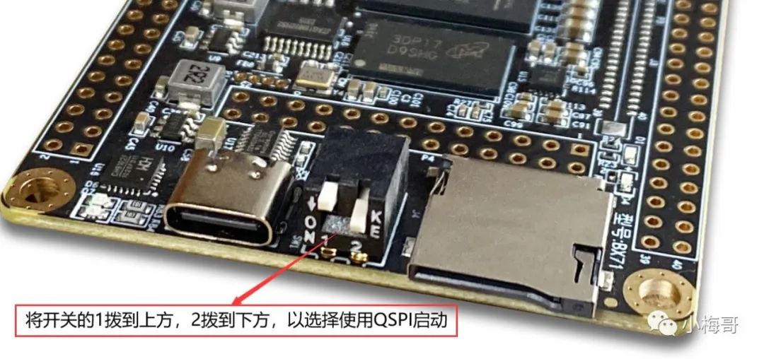
After programming, switch the startup mode of the development board to QSPI. Disconnect the Type-C data cable.
Driver Installation
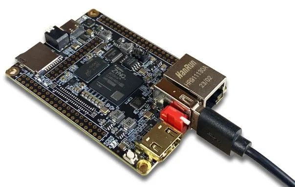
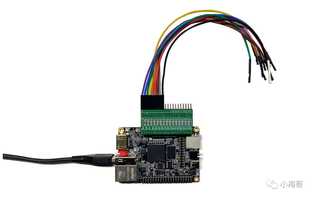
Using the provided USB Type-A male-to-male data cable, connect one end to the BX71 core board’s TYPE-A female port and the other end to the USB port of the computer.
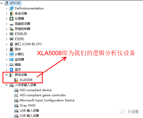
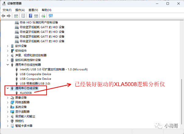
In the Device Manager, you will find a device named XLA5008. This is our logic analyzer device.
Open the zadig.exe software under the driver folder, and the software will automatically detect the XLA5008 device. If it does not default to XLA5008, you can click the dropdown arrow on the right to find and select it.
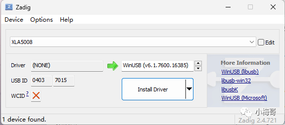
Click the Install Driver button to start the driver installation. The installation process may take 1-2 minutes.
Once the driver installation is complete, you will see the XLA5008 with the installed driver under the Universal Serial Bus devices in the Device Manager.
Using the Upper Computer Software
Run the pulseview.exe software in the app to open the logic analyzer upper computer, which will automatically scan for our XLA5008 logic analyzer.
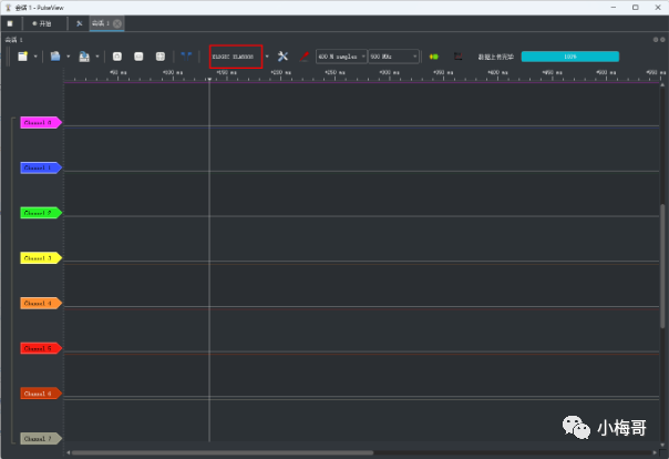
Click Start to begin capturing waveforms.
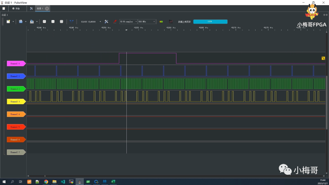
Please note that capturing waveforms requires the use of a front-end signal conditioning board; otherwise, in high-frequency situations, signal overshoot may cause glitches, affecting protocol analysis.
Video Demonstration
We have recorded a video demonstrating the specific operation methods, which you can view.
Document Download
All files mentioned in the article can be downloaded from the comments section or by messaging me directly.