Build a 100MHz Logic Analyzer with Raspberry Pi Pico
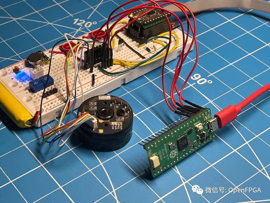
Transform a Raspberry Pi Pico (or any RP2040 board) into a simple logic analyzer in 5 minutes.
Introduction
A logic analyzer is an electronic instrument that captures and displays multiple signals from digital systems or circuits. It can convert captured data into timing diagrams, protocol decoding, state machine tracking, opcodes, or correlate opcodes with source-level software. Logic analyzers have advanced triggering capabilities and are very useful when users need to observe timing relationships between many signals in a digital system.
μLA is SUMP/OLS compatible logic analyzer firmware for RP2040-based boards.
Features
-
16 Channels -
100 MHz Sampling Rate (up to 250 MHz with proper optimization (overclocking)), capturing 1 sample per system clock cycle -
200 KB Memory -
Fast triggering using PIO
Supported Hardware
-
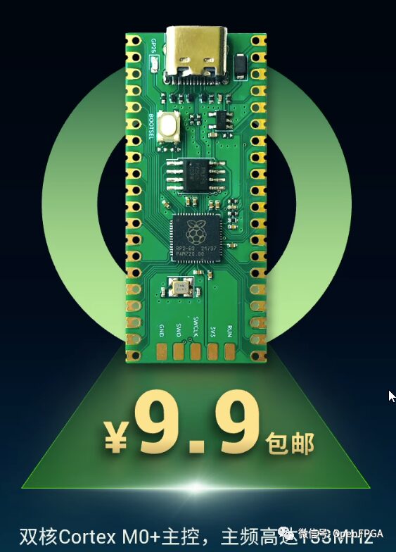
Raspberry Pi Pico -
RP2040-zero -
All RP2040-based boards (must have USB connection)
Installation
-
Download the latest µLA firmware from the link below
https://github.com/dotcypress/ula/releases
-
While connecting the development board to the computer, hold down the BOOTSEL button -
Copy the previously downloaded firmware file to the RP2040 -
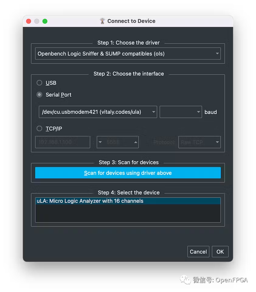
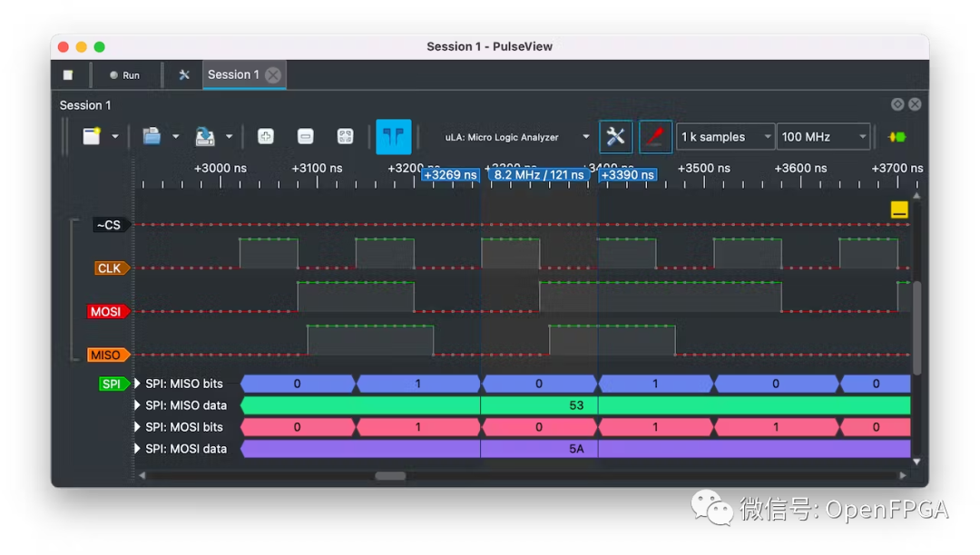
Use PulseView or sigrok-cli for host-side capture and analysis
https://sigrok.org/wiki/PulseView
https://sigrok.org/wiki/Sigrok-cli
-
Enjoy
Code
https://github.com/dotcypress/ula
https://sigrok.org/wiki/PulseView
https://sigrok.org/wiki/Sigrok-cli
Verilog “Seven Deadly Sins”
[Vivado Matters] How to Find Official Examples and How to Use Them
“Undetectable Cheats”, Why Use FPGA as a “DMA” Bridge for FPS Games
Optimizing FPGA HLS Design