
0x01 Introduction
Recently, I purchased a logic analyzer. I had limited exposure to digital signals and inter-chip communication before, but I have been studying these topics intensively over the past few days and now I would like to document my findings for future reference.
0x02 What is a Logic Analyzer
Introduction to Logic Analyzers
A logic analyzer is an instrument that captures and displays digital signals from a test device using a clock, primarily for timing analysis. Unlike oscilloscopes, which display multiple voltage levels, logic analyzers typically show only two voltage levels (logic 1 and 0). After setting a reference voltage, the logic analyzer determines the signal being measured via a comparator: signals above the reference voltage are classified as High, while those below are classified as Low, creating a digital waveform between High and Low.
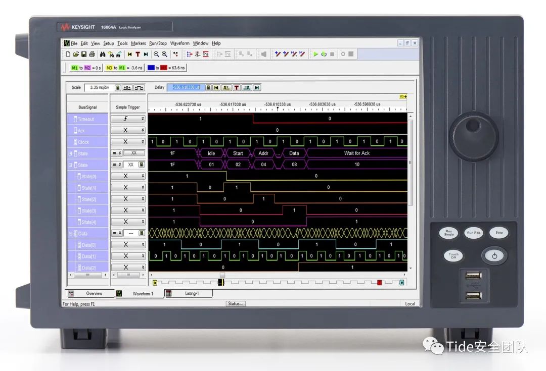
A logic analyzer is an instrument used to capture and display digital circuit signals. Its primary function is timing analysis. Unlike oscilloscopes, which can display various voltage levels, a logic analyzer only shows two levels: logic 1 and logic 0, along with an uncertain state x.
After setting two reference voltages, the logic analyzer uses a comparator to determine the measured signal: signals above the higher reference voltage are classified as logic 1, those below the lower reference voltage as logic 0, and those between the two reference voltages as uncertain x.
Working Principle of Logic Analyzers
The measurement principle of a logic analyzer involves comparing the input signal with a set threshold voltage at a specific frequency. When the input level exceeds the threshold voltage, it is classified as logic 1; when it falls below the threshold, it is classified as logic 0.
The operation of a logic analyzer involves data acquisition, storage, triggering, and display. It uses digital storage technology, allowing data acquisition and display to occur separately or simultaneously. If necessary, stored data can be displayed repeatedly to facilitate analysis and research.
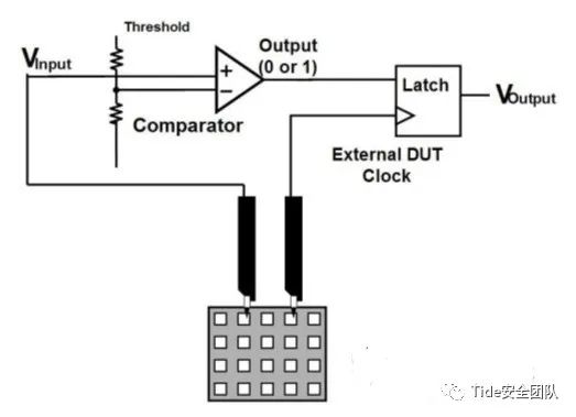
To connect the measured system to the logic analyzer, the logic analyzer’s probe (which combines several probes into a compact design for probing high-density integrated circuits) monitors the data flow of the system under test, sending parallel data to the comparator. The input signal is compared against the externally set threshold level; signals exceeding the threshold output a high level on the corresponding line, while those below output a low level, shaping the input waveform.
The shaped signal is sent to the sampler, which samples the data under clock pulse control. The sampled signals are sequentially stored in memory. The sampling information is organized in memory using a first-in, first-out principle. Upon receiving a display command, the information is read out in order and displayed according to the set display method.
Advantages of Logic Analyzers
In the field of electronic testing, oscilloscopes were the first testing devices, originating from radar scanning principles. They collect and reproduce signal waveforms based on traditional analog signal and circuit testing.
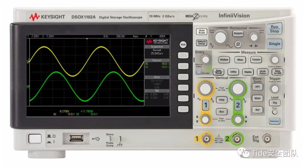
1. When measuring digital signals, oscilloscopes are typically used to observe whether a signal exists and its quality, while logic analyzers are mainly used to analyze the timing of signal high and low levels, as well as the data being communicated.
2. Logic analyzers have a sufficient number of input channels; oscilloscopes commonly have single, dual, or four channels, while logic analyzers typically have 8, 16, 32, or more channels, allowing them to measure multiple signal states, especially parallel data. The more channels available, the better the analysis of all channels.
3. They have delay capabilities, allowing them to store data for longer periods. Oscilloscopes display data in real-time, which means they can only show a small segment of data, resulting in low storage depth. Logic analyzers, however, have greater storage depth, enabling them to store large amounts of data for later analysis.
4. They offer various flexible triggering functions that allow for selecting the data to be captured and debugging program segments during system operation. Oscilloscopes typically only have edge-triggering and voltage setting triggers, whereas logic analyzers can set more complex triggers, including parallel data.
5. They possess powerful data analysis capabilities. For complex protocols, oscilloscopes display waveforms, while logic analyzers can directly decode hexadecimal data. They can conveniently display parsed data in various formats, including ASCII, binary, decimal, and hexadecimal, making it more intuitive.
In the analog era, oscilloscopes had irreplaceable advantages, but in the digital world, logic analyzers offer more powerful functions and can be considered essential tools for analyzing digital communications.
Common Use Cases for Logic Analyzers
1. Observing waveforms
Check for glitches, interference, and correct frequency in the measured waveforms;
2. Timing measurement
Perform timing analysis of the measured signal to eliminate operational conflicts and timing coordination issues;
3. Assisting analysis
Utilize the comprehensive analysis functions of the logic analyzer to analyze bus signals or high-level protocols, accelerating development progress;
4. Error detection
Use the powerful triggering functions of the logic analyzer to capture errors and eliminate hidden faults in the system, enhancing product reliability.
0x03 Using a Logic Analyzer
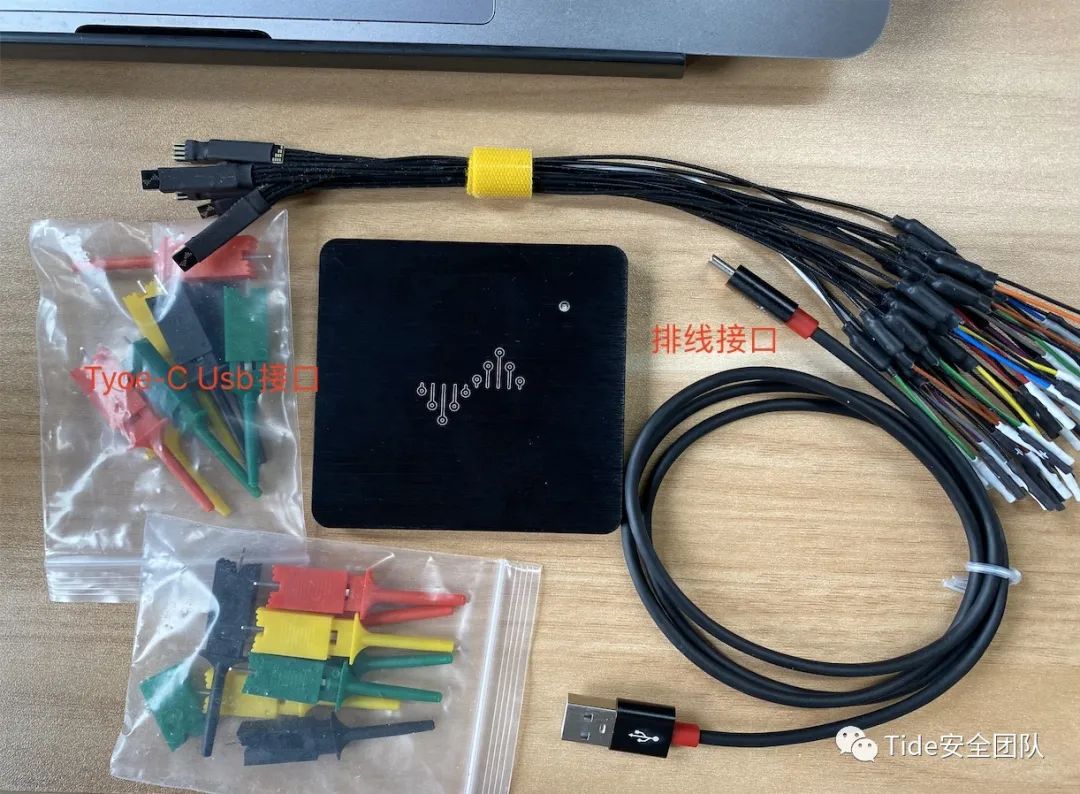
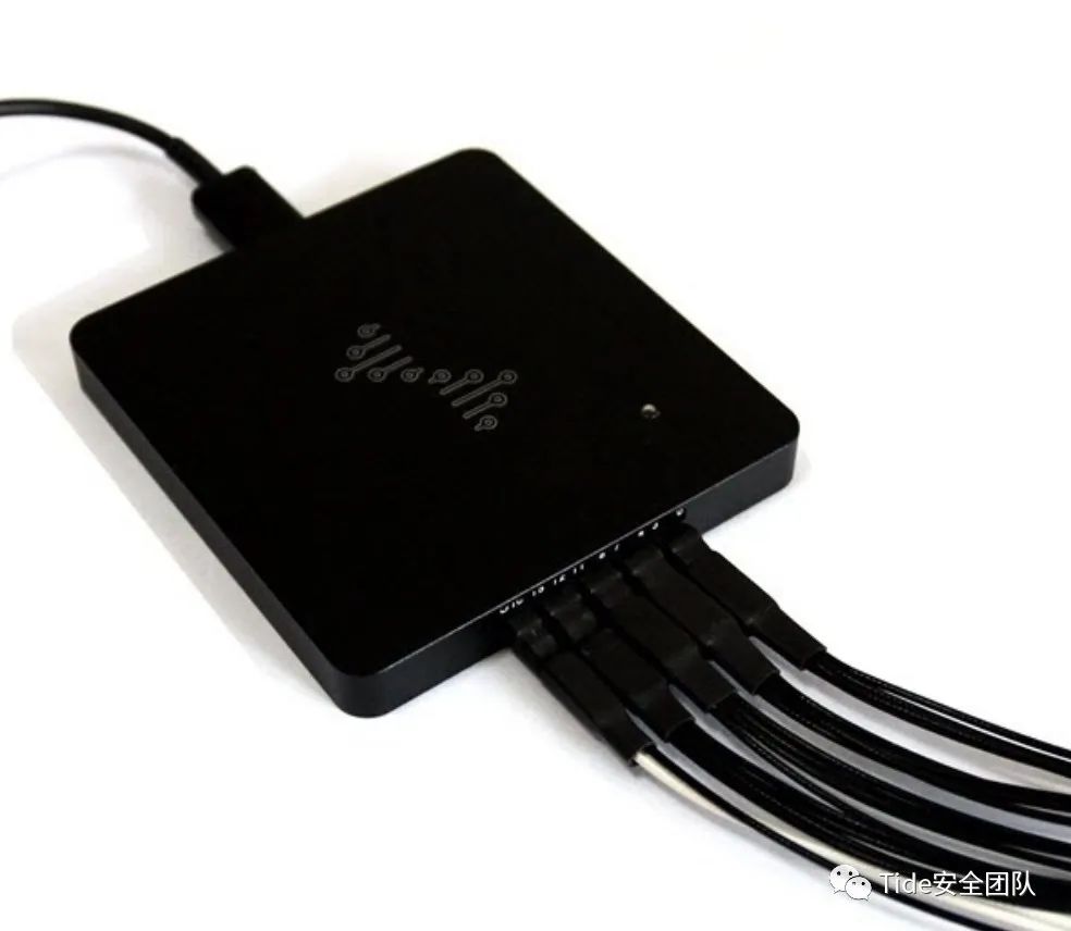
Below is a brief overview of how to use a logic analyzer, taking the DreamSource logic analyzer as an example:
Using a logic analyzer connected to digital signals, capturing and analyzing digital signals generally involves the following four steps:
1. Connect the logic probe to the device under test (DUT)
2. Set the clock mode and triggering conditions
3. Capture the measured signal
4. Analyze and display the captured data
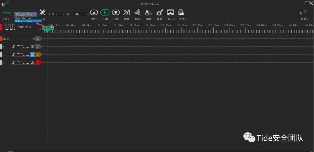
1. Open the DreamSource DSView software
Select the DSLogic Plus device.
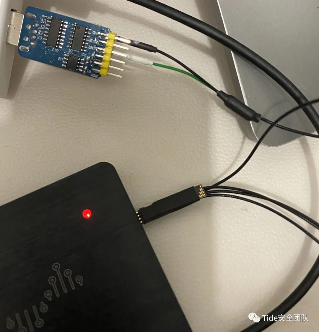
2. Hardware channel connection
Connect the logic analyzer’s GND to the URAT serial port’s GND to ensure signal integrity. Then connect the logic analyzer’s channels to the test pins (RX/TX).
3. Capture options:
Operating mode
In DSView, the logic analyzer can capture signals in either stream or buffer mode. In stream mode, different numbers of channels have different sampling rates, while in buffer mode, the sampling rate is fixed.
Since we are only using three channels, we can simply select stream mode.
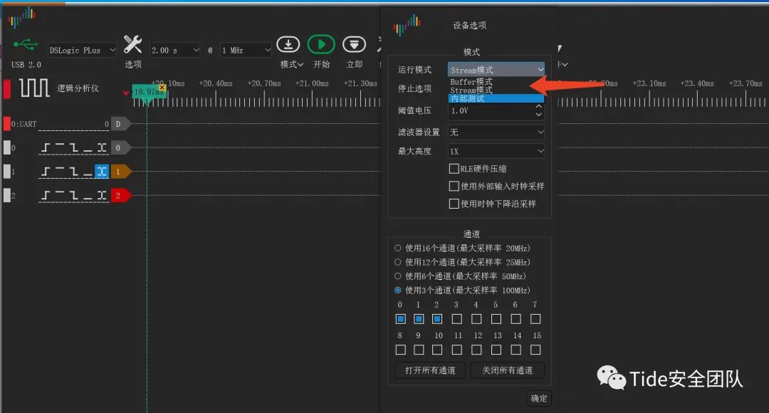
Voltage threshold
The voltage threshold in DSView can be set between 0 and 5V. For a typical 3.3V digital system, setting the threshold voltage to 1.0V is appropriate; setting it too low or too high may lead to inaccurate signals.
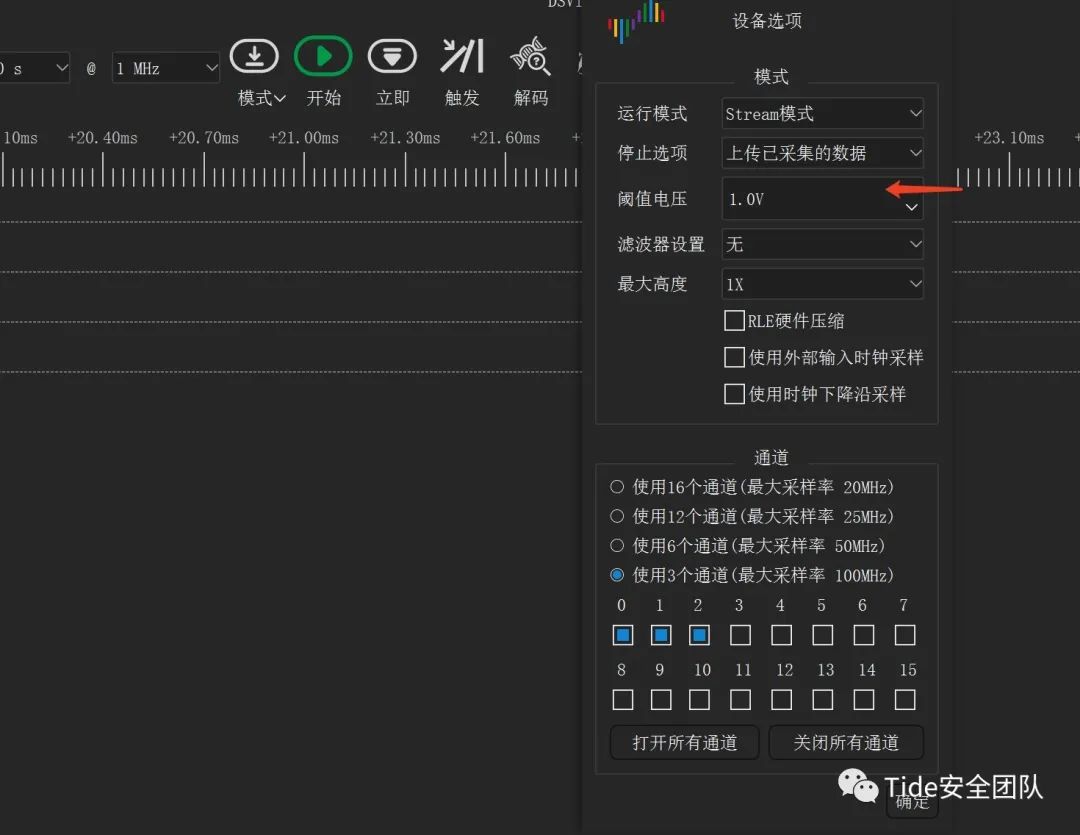
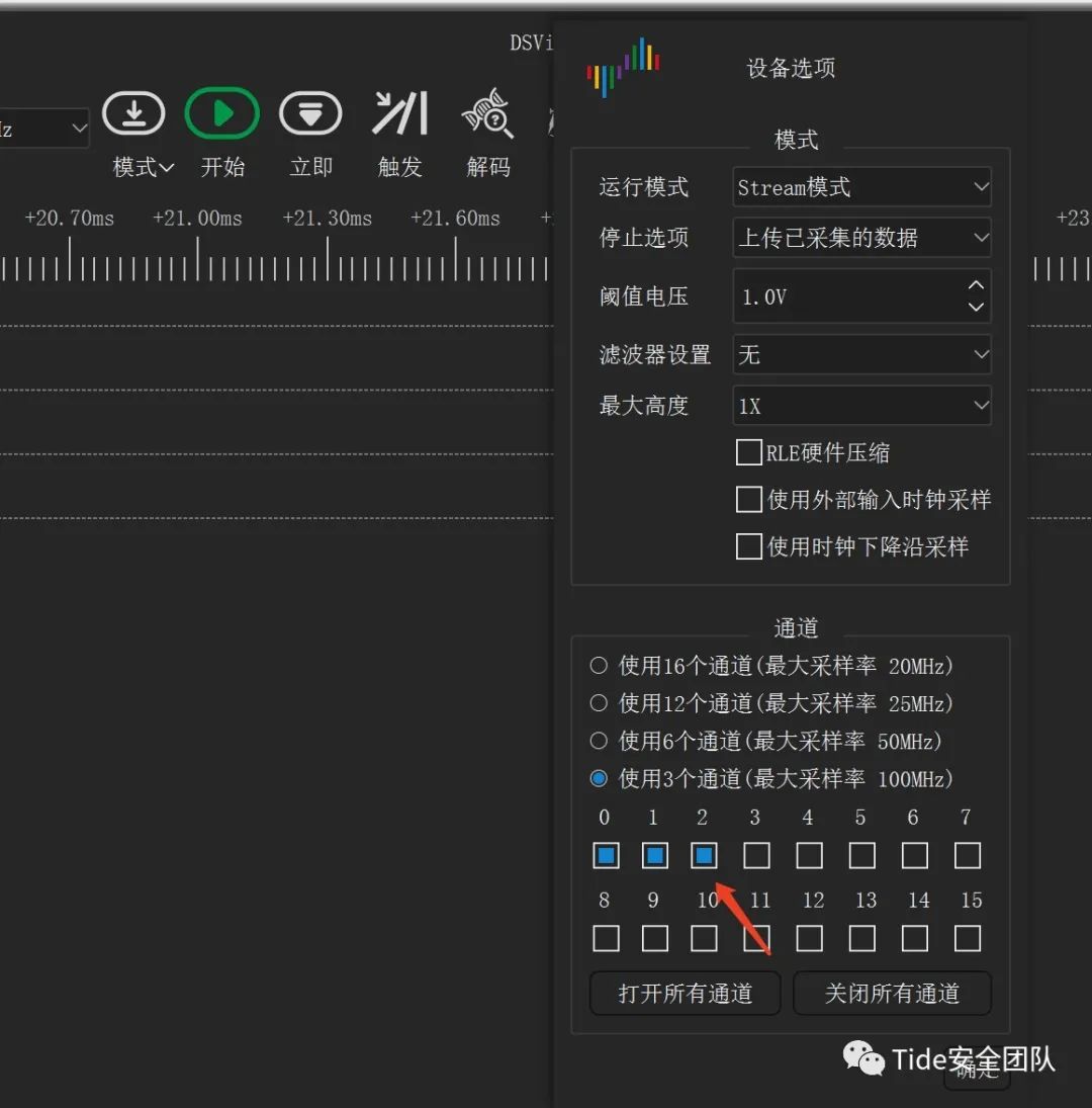
Select channels
The logic analyzer has 16 channels, but to observe the waveforms better, we will only use 3 channels.
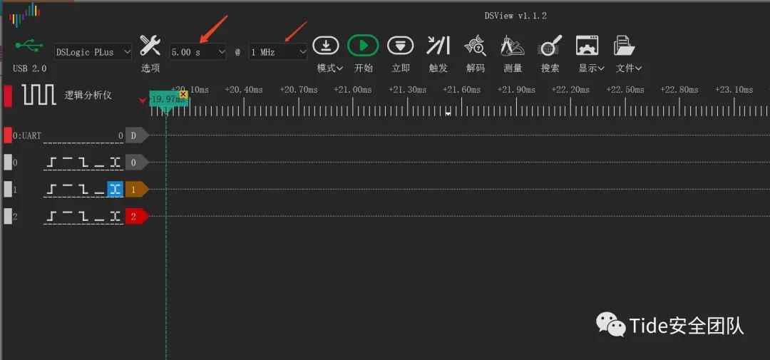
3. Capture duration and sampling rate: It is important to understand that both the sampling rate and the sampling duration are related to storage depth. Storage depth = sampling rate * window display duration. Set the sampling rate to 1MHz and the sampling time to 5s.
4. Trigger settings
Due to the depth limitations of the logic analyzer, if no trigger settings are applied, the capture will stop once the set storage depth is reached. During actual signal acquisition, the initial segment of captured signal may be useless, yet it still occupies storage space. In such cases, we can improve storage depth utilization by setting triggers.
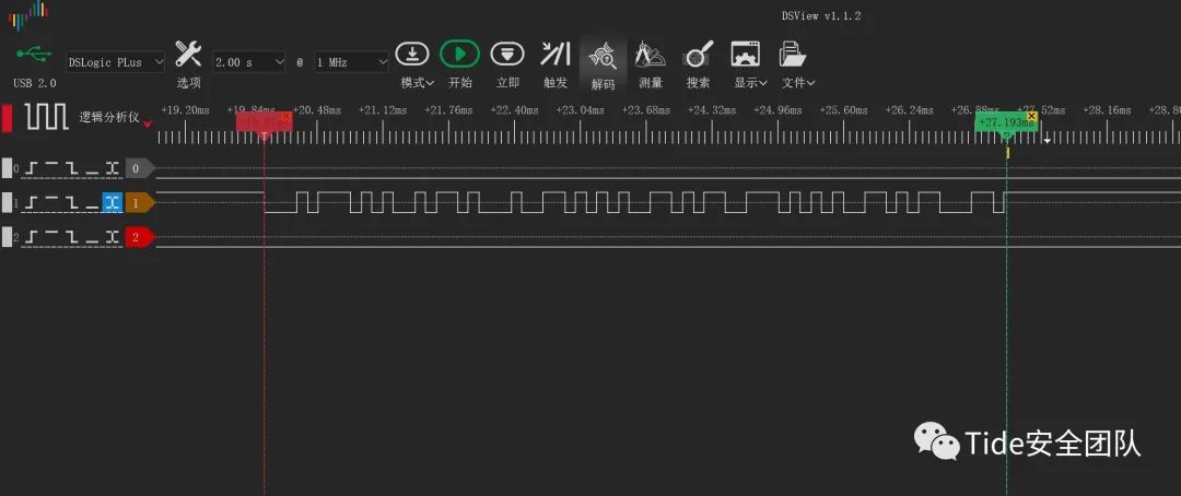
Simple triggering can be achieved by setting the trigger conditions for a specific channel. For example, we can set the trigger condition to capture signals when channel 1 generates a dual-edge signal, triggering signal acquisition when channel 1 produces either a rising or falling edge.
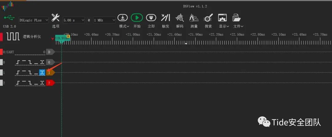
For instance, if we want to capture UART serial port signals, which are typically high when there is no data, we can set a falling edge trigger. Once we click to start capturing, the logic analyzer will not save the captured signal until the trigger conditions are met, at which point it will begin actual signal acquisition and store the captured signals in memory.
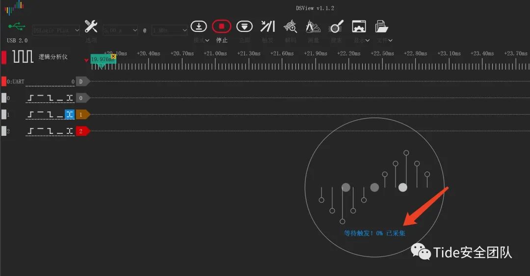
We use a serial port debugging assistant to send test data ‘tidesec’ for testing, selecting the COM port connected to the UART and setting the baud rate to 9600.
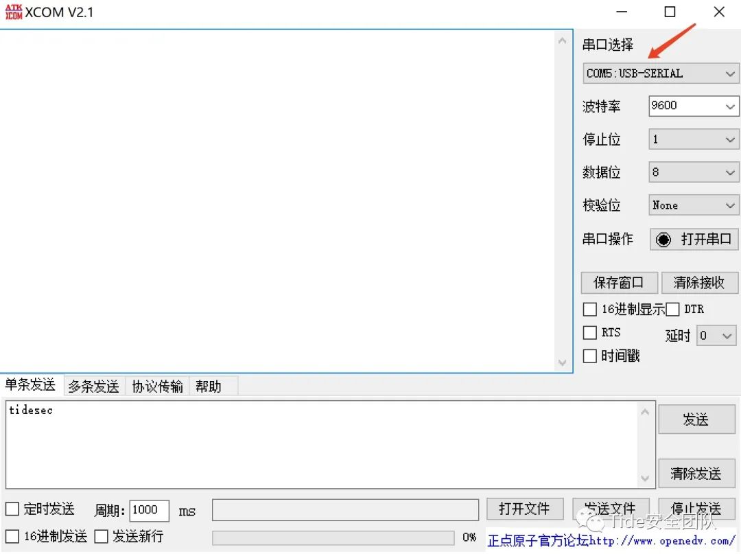
After clicking send, the trigger conditions for signal acquisition are activated, and the signal acquisition begins, storing the captured signals in memory.
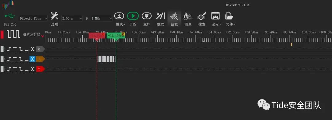
5. Capturing waveforms
Unlike oscilloscopes, which display data in real-time, logic analyzers require you to click start to begin capturing waveforms, continuing until the set storage depth is filled.
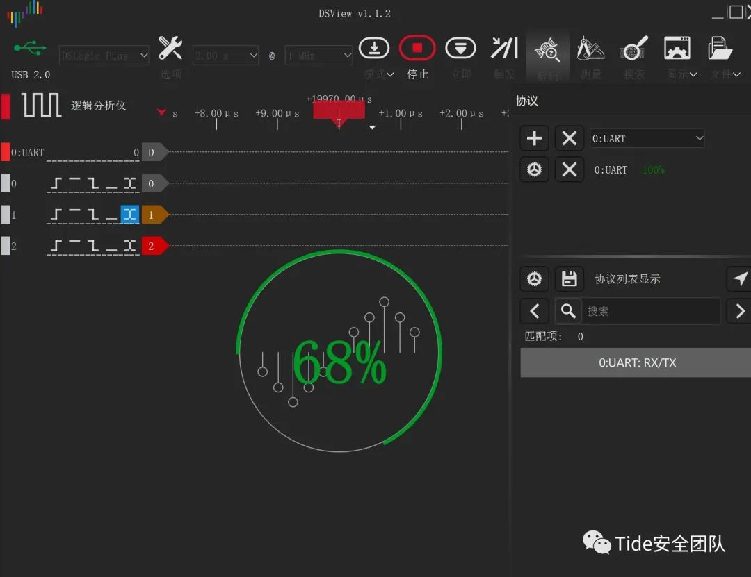
6. Set protocol decoding If the captured waveforms follow standard protocols, such as UART or I2C, the logic analyzer will come with dedicated decoders.
By setting the decoder, the data can be directly parsed and displayed in various formats, including hexadecimal, binary, and ASCII.
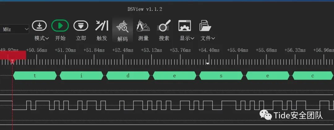
The decoding was successful, displaying the characters we tested with the serial port debugging assistant, sending the test data ‘tidesec’.
0x04 Reference Links: https://zh.m.wikipedia.org/zh/%E9%80%BB%E8%BE%91%E5%88%86%E6%9E%90%E4%BB%AA https://www.pianshen.com/article/1040719934/ https://www.eefocus.com/test-measurement/423995E
N
D
Close
About
Us
Team
The Tide Security Team was officially established in January 2019, under the Xinxin Information umbrella, focusing on research in internet offense and defense technologies. The team is dedicated to sharing high-quality original articles, open-source security tools, and exchanging security technologies. Our research spans various fields, including network offense and defense, system security, web security, mobile terminal security, secure development, IoT/industrial control security, and AI security.
As a “provincial-level key technology laboratory for security”, we have established joint technical laboratories with several notable universities and enterprises, including Harbin Institute of Technology, Qilu Bank, Liaocheng University, and Transportation College. Over the past three years, we have conducted more than 60 research projects in network security technology, obtaining over 30 types of independent intellectual property rights and more than 20 provincial and municipal science and technology project approvals. Our research results are applied to core technology research for products, tackling national key science and technology projects, and providing professional security services. Interested individuals in security can join or follow us.