
In embedded systems, efficient data transmission is key to connecting processors with peripheral devices. SPI (Serial Peripheral Interface), as a high-speed synchronous serial communication protocol, has become the preferred solution for interactions with peripherals such as sensors, memory, and display modules due to its flexible configuration, full-duplex capability, and low-latency characteristics. This article will comprehensively analyze the design principles and technical features of SPI peripherals from the perspectives of hardware architecture, communication modes, data transmission mechanisms, and core advantages.
 Overview of SPI: The Cornerstone of Synchronous Communication
SPI is a synchronous serial interface based on a master-slave architecture, employing full-duplex or half-duplex communication modes, and supports high-speed data transmission. Its core features include:
Clock Synchronization: The controller (master device) provides the clock signal (SCLK) to ensure data synchronization.
Programmable Configuration: Data length (1-16 bits), baud rate (125 selectable options), and operating modes can be flexibly adapted to requirements.
Efficient Hardware Support: Transmit/Receive FIFO reduces interrupt overhead, and a double-buffered receive mechanism enhances throughput efficiency.
Multi-Device Expansion: Multi-peripheral bus management is achieved through chip select signals (SS/CS).
 Hardware Architecture and Operating Modes
▋Master-Slave Architecture and Role Definition
SPI communication requires clear definitions of the roles of the controller (Master) and the peripheral (Slave):
Controller: Generates the clock signal (SCLK) and initiates and controls data transmission.
Peripheral: Responds to the controller’s clock and synchronously sends or receives data.
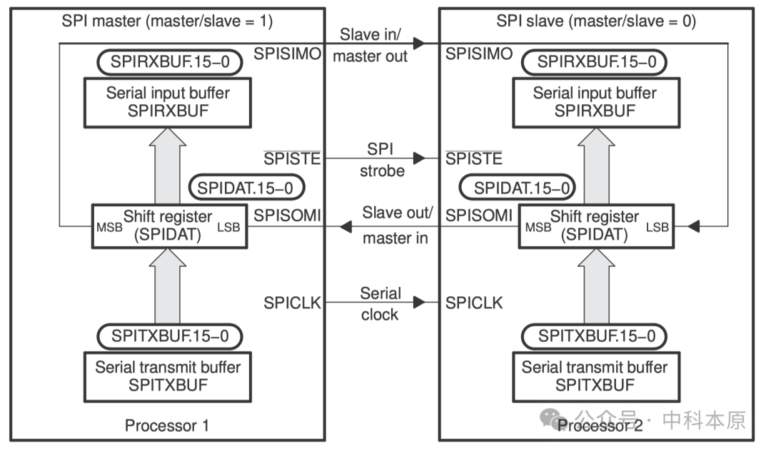
Figure 1: Master/Slave Mode
▋Communication Modes
SPI supports three data transmission modes to meet different scenario requirements:
Mode 1: The controller sends data while the peripheral sends dummy data (unidirectional transmission).
Mode 2: The controller and peripheral simultaneously send valid data (full-duplex interaction).
Mode 3: The controller sends dummy data while the peripheral actively sends data (peripheral-driven).
▋Interface Wiring
Three-Wire Full-Duplex: SCLK (clock), MOSI (Master Out Slave In), MISO (Master In Slave Out).
Two-Wire Half-Duplex: Shared data line (e.g., single-wire bidirectional transmission), requiring protocol layer management for direction switching.
 Data Transmission Mechanism and Process
▋Registers and Buffers
SPIDAT: A 16-bit shift register that directly participates in data input/output operations.
SPITXBUF: Transmit buffer that automatically loads data into SPIDAT after writing.
SPIRXBUF: Receive buffer where data is copied from SPIDAT after reception is complete, supporting a double-buffering mechanism.
▋Data Transmission Sequence
Data Writing:The controller or peripheral writes the data to be sent into SPITXBUF (or directly into SPIDAT).
Clock Start:After the controller writes to SPIDAT, the SCLK signal is automatically generated to start transmission.
Bit-Level Shifting: Data shifts out from the MSB (Most Significant Bit) of SPIDAT, while simultaneously shifting into the LSB (Least Significant Bit) of the other device.
Cyclic Shifting: Repeated shifting until the specified number of bits is transmitted.
Data Latching: Received data is copied from SPIDAT to SPIRXBUF, triggering an interrupt flag (SPI INT).
Interrupt Handling:If interrupts are enabled (SPI INT ENA=1), the CPU reads SPIRXBUF and processes the data.
▋Key Considerations
Sending Limitations: SPI does not support double-buffered sending; ensure the current transmission is complete before writing new data to avoid data corruption.
Overflow Prevention: The receiving end must read SPIRXBUF before the next transmission is complete to prevent data overwriting.
 Data Alignment and Bit Processing
SPI employs a hardware-level data alignment mechanism:
Sending Alignment:
When the data length is less than 16 bits, it must beleft-aligned before writing to SPIDAT (padding high bits with zeros).
For example: To send 9 bits of data, it must be left-shifted by 7 bits before writing the high 9 bits to SPIDAT.
Receiving Alignment:
Received data is automaticallyright-aligned in SPIRXBUF, and unused high bits must be masked by software.
For example: When receiving 9 bits of data, the high 7 bits of SPIRXBUF must be masked to extract the valid value.
 Core Advantages and Application Scenarios
▋Technical Advantages
High-Speed Transmission: Synchronous clock driving supports MHz-level baud rates, suitable for scenarios with high real-time requirements.
Full-Duplex Efficiency: Data is sent and received simultaneously, enhancing bandwidth utilization.
Simplified Hardware: No complex addressing protocols are needed; multiple devices can be directly connected via chip select signals.
▋Typical Applications
Sensor Interfaces: Real-time data acquisition from sensors such as temperature sensors (DS18B20) and accelerometers (MPU6050).
Storage Devices: Data read/write operations for Flash memory.
Display Drivers: High-speed refresh of display memory for OLED/LCD screens.
Multi-Device Systems: Managing arrays of peripherals (e.g., IoT nodes) through multiple chip select signals.
Conclusion
SPI peripherals, with their simple hardware design, high-speed synchronous transmission capabilities, and flexible configuration options, have become the core solution for short-distance communication between devices in embedded systems. Whether for sensor data acquisition, memory expansion, or real-time display control, SPI can meet stringent performance requirements through efficient hardware collaboration. With the evolution of the Internet of Things and edge computing, SPI will continue to play an important role in connecting high-density peripherals with processors in the technological ecosystem.
 Previous Recommendations
Detailed Explanation of DSP General Parallel Port uPP Technology
How Dual-Area Architecture Balances Security and Performance?
The “Eye of Fire” in Chip Design: DFT Testability Design