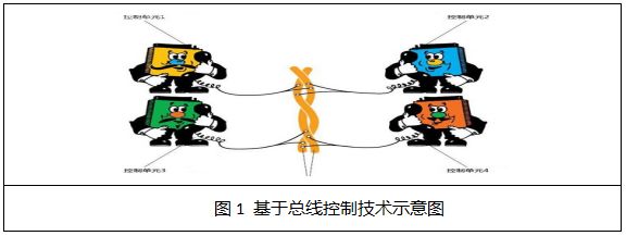
As the automobile industry develops, the number of electrical devices in vehicles is increasing. For each additional electrical device, two power lines must be added. Simultaneously, each electrical device requires two additional switch wires. The rapid increase in electrical devices in vehicles has led to a corresponding rise in switch wires. This increase in electrical functions has also caused a dramatic rise in the number of electronic devices in cars, all of which share a common power source. Given the trend of increasing electrical devices, is it possible to avoid increasing the total number of switch wires and instead use a single bus? This led to the development of the automotive equipment switch wire common bus technology. On the other hand, as the intelligence of electrical devices increases, information exchange between them becomes necessary, naturally requiring the introduction of on-board network technology. Below is an overview of automotive bus and on-board network technology. 1. Automotive Bus The automotive bus refers to the communication network that interconnects “low-level automotive devices or instruments” within the on-board network. One can understand it as follows: in the past, to make a phone call, there had to be a central switchboard and many extensions. An extension could call another extension through the switchboard. This setup reduces the number of connection wires between extensions. Similarly, the increase in functions has led to a dramatic rise in the number of electronic devices in vehicles, which need to communicate with each other, thus leading to the development of a bus system similar to the central switchboard and extensions, using a single bus to connect different devices.
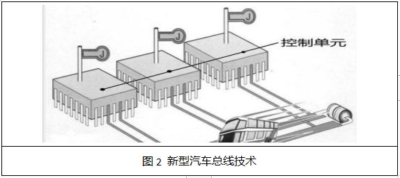
Statistics indicate that modern automobiles can have up to 1500 electrical nodes (devices), with wire lengths reaching 2000 meters, and this number is expected to double approximately every ten years. Traditional automotive electronics use a point-to-point communication method with little interconnection, which means that if a point-to-point communication method is still used with an increasing number of electrical devices, it will inevitably lead to a vast wiring system, exacerbating the conflict between bulky wiring harnesses and the limited space available in vehicles. From both material cost and work efficiency perspectives, traditional wiring models cannot adapt to the development of modern automobiles. On the other hand, the real-time requirements of various electronic systems are also increasing, and each control unit has different real-time requirements, especially for shared information such as engine speed, wheel speed, and throttle position. Thus, new automotive bus technologies have emerged, as shown in Figure 2.
The automotive bus is the foundation for achieving digital networking. The four major bus technologies commonly used in vehicles are CAN, LIN, FlexRay, and MOST bus.
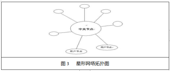
1. CAN Bus Technology The CAN bus is a communication protocol developed by Bosch in Germany in 1986 for automotive applications, designed to facilitate data exchange between numerous electronic control units (ECUs) in modern vehicles. The CAN bus, also known as the automotive bus, stands for “Controller Area Network.” The “controller” refers to automotive electrical devices. The CAN bus is a serial communication network that effectively supports “distributed control” and “real-time control,” standardized by ISO11898 and ISO11519, and has become the standard protocol for automotive networks in Europe, representing the mainstream development trend of automotive electronic control networks. Many renowned automotive manufacturers, such as Volkswagen, Benz, BMW, Porsche, and Rolls-Royce, have adopted the CAN bus for data communication within their automotive control systems. The CAN bus connects various individual control units in a certain form (mostly star topology, as shown in Figure 3) to form a complete system.
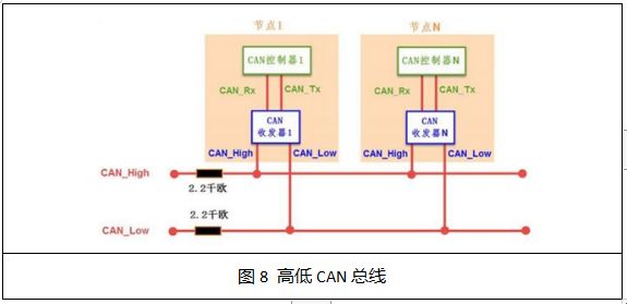
1. Structure and Units of the CAN Bus The CAN bus has high and low variants, with N units, as shown in Figure 4. Explanation:
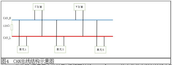
(a) The CAN transceiver (the unit in the schematic) determines the bus level based on the potential difference between the two lines CAN_H and CAN_L; (b) In practice, CAN_H and CAN_L are composed of twisted pairs; (c) The resistors at the data transmission terminals prevent data transmission reflections that could corrupt the data, with a resistance value of 120Ω; (d) CAN communication is essentially data transmission between units. (1) Controller The operation controller, as shown in Figure 5, is one of the five components of the microprocessor (CPU).
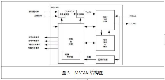
Its function is to generate various operational control signals. The operation controller (OC) mainly includes a pulse generator, control matrix, clock pulse generator, reset circuit, and start-stop circuit control logic (Note: these components are crucial for microprocessor designers, but users of microprocessors do not need to be overly concerned about them). (2) Electronic Control Unit (ECU) From a functional perspective, it is a dedicated microcontroller for automobiles, also known as an automotive-specific microcontroller, as shown in Figure 6.
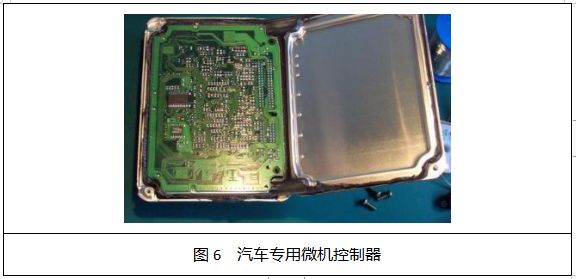
It comprises a microprocessor (CPU), memory (ROM, RAM), input/output interfaces (I/O), analog-to-digital converters (A/D), and large-scale integrated circuits for shaping and driving, similar to ordinary microcontrollers. (3) Serial Communication Protocol Serial communication refers to the process of transmitting data bit by bit over a single data line. (i) During transmission, the first data is sent, followed by the second, and so on. (ii) When receiving data, each bit is received sequentially from a single data line, and then they are combined into complete data. (iii) In long-distance data communication, serial communication is generally used, which has the advantages of occupying less communication lines and lower costs. (iv) A protocol refers to the agreed communication format between both parties. 2. Principles and Characteristics of the CAN Bus Communication System (1) The structure of the bus communication system is shown in Figure 7.
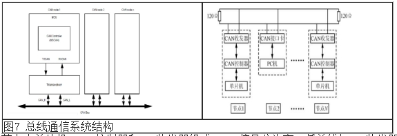
The nodes consist of a microcontroller, CAN controller, and CAN transceiver. The CAN signal is divided into high and low buses linked with the CAN transceiver, as shown in Figure 8.
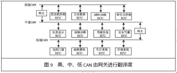
(2) Characteristics of bus communication: (a) Communication is non-hierarchical, allowing any node on the network to actively send information to other nodes at any time. (b) Nodes on the network can be divided into different priority levels. When two nodes transmit information simultaneously, the node with the higher priority will have precedence. The number of nodes can reach 110, with each frame containing 8 valid bytes, and each frame of information includes CRC checks and other error detection measures, resulting in a very low data error rate. (c) CAN has high, medium, and low classes, with gateways between them, as shown in Figure 9.
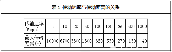
(d) Data transmission (reception) methods can be point-to-point, one-to-many, or global broadcast. (e) At communication speeds below 4Kbps, the maximum direct communication distance can reach 10km; at the highest communication speed of 1MB/s, the maximum distance is 40m. (f) Communication media can use twisted pairs, coaxial cables, and fiber optics, with inexpensive twisted pairs typically used. When using unshielded twisted pairs for transmission, the relationship between transmission speed and distance is shown in Table 1. (g) In cases of severe errors, nodes have the capability to automatically shut down the bus, disconnecting themselves from the bus to prevent interference with other operations on the bus.
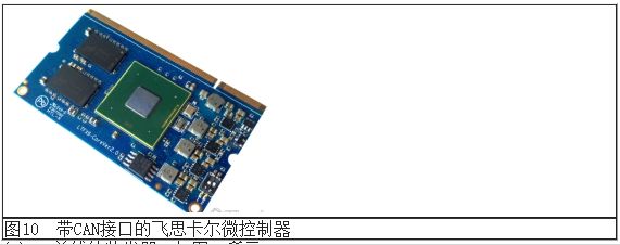
3. Freescale Microcontrollers with CAN Interface (a) Freescale microcontroller with CAN interface, as shown in Figure 10.
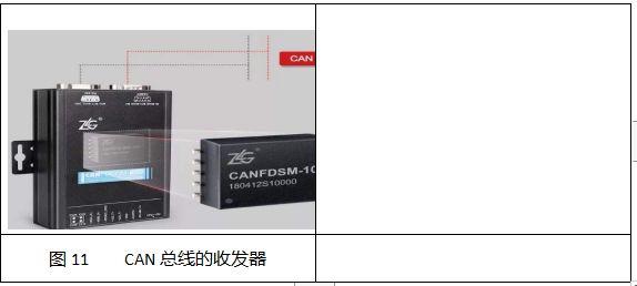
(b) The CAN bus transceiver, as shown in Figure 11.
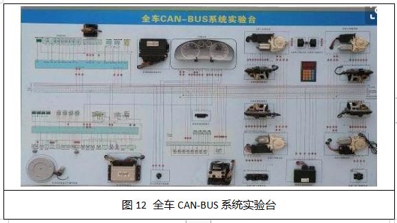
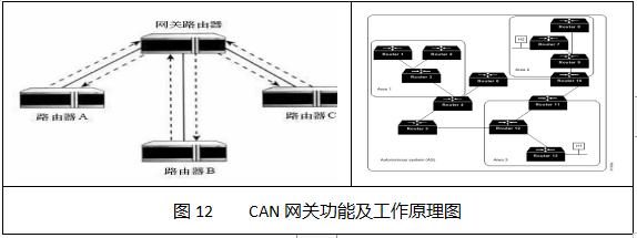
(c) The entire vehicle CAN-BUS system experimental platform, as shown in Figure 12.
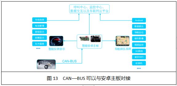
(d) CAN-BUS can interface with Android motherboards, as shown in Figure 13.
(2) LIN Bus Technology LIN, as a supplement to CAN, has become an international standard. LIN is a new type of open serial communication protocol jointly launched by Motorola and Audi among other well-known enterprises. The cost savings of LIN compared to CAN are due to its single-wire transmission, low implementation costs in silicon chips (hardware or software), and the absence of quartz or ceramic resonators in subordinate nodes. This comes at the cost of lower bandwidth and a limited single-master bus access method. LIN consists of a master node and one or more slave nodes, as shown in the figure.
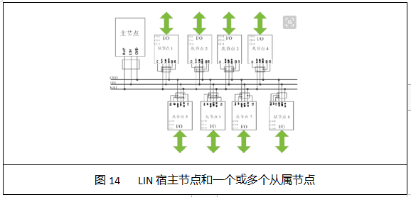
The typical number of nodes in a LIN network can reach 12. It is primarily used in distributed electronic control systems within vehicles, especially in digital communication scenarios aimed at intelligent sensors or actuators, such as applications in power windows, seat adjustments, and lighting controls. Taking window control as an example, as shown in Figure 15.
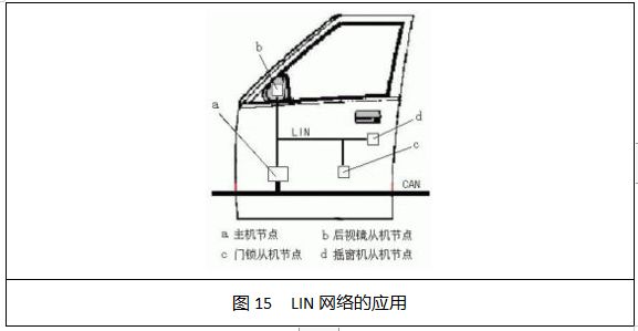
In the car door, there are door locks, window switches, window raising motors, and operation buttons, which can all be interconnected through a single LIN network. Through a CAN gateway, the LIN network can also exchange information with other systems in the vehicle, achieving richer functionalities. The function and working principle of the CAN gateway are illustrated in Figure 16.
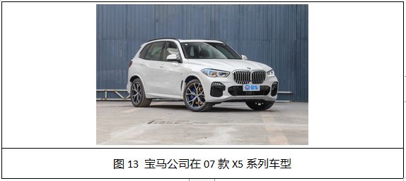
(3) FlexRay Bus FlexRay is a bus technology designed for in-vehicle networking, based on intelligent networked automotive bus technology, utilizing a time-triggered mechanism, and characterized by high bandwidth and good fault tolerance. It has certain advantages in terms of real-time capability, reliability, and flexibility. FlexRay is a high-speed, deterministic bus technology for automotive applications that combines event-triggered and time-triggered methods, featuring high network utilization and system flexibility, making it the backbone network for the next generation of automotive internal networks. Currently, FlexRay is primarily used in safety-critical drive-by-wire systems and power systems. The FlexRay bus is a new communication standard jointly established by BMW, Philips, Freescale, and Bosch, and has been applied in BMW’s high-end vehicles. FlexRay can be used in passive bus and star network topologies, or in a combination of both. Both topologies support dual-channel ECUs, and the dual-channel architecture provides redundancy, effectively doubling the available bandwidth, with a maximum data transfer rate of 10Mbps per channel. This ECU integrates multiple system-level functions to reduce production costs and complexity. BMW first applied FlexRay technology in the electronic control shock absorber system of the 2007 X5 series models (as shown in Figure 13).
Freescale microcontrollers and NXP transceivers are used to achieve better ride comfort, safety during driving, and high-speed responsiveness. They can monitor data related to vehicle speed, longitudinal and lateral acceleration, steering wheel angle, body and tire acceleration, and ride height, while minimizing changes in load applied to the tires and vibrations of the chassis. The application of FlexRay bus technology will increase as drive-by-wire systems are promoted, but it will take some time to advance this process. CAN technology has already been recognized by the industry, and it is expected that FlexRay will interface with CAN bus through gateways for drive-by-wire systems. (4) MOST Bus MOST stands for “Media Oriented System Transport,” a bus system specifically designed for in-vehicle multimedia applications to meet the demands of high-end automotive entertainment devices. It can be used in in-vehicle camera systems and can achieve real-time transmission of audio and video. Since the introduction of MOST technology in BMW’s 7 series vehicles, its popularity has surged in recent years. 1. MOST Bus Characteristics (a) It can achieve a data transmission speed of 24.8 Mbit/s while ensuring low costs, which not only reduces the size of the connection harness between components and lowers noise but also alleviates the burden on system developers. (b) It can operate regardless of whether a master control computer is present, supporting real-time processing of audio and compressed images. (c) It supports both synchronous and asynchronous data transmission, with transmitters/receivers embedded with a virtual network management system. (d) It provides standards for MOST devices, facilitating a simple application system interface and supporting various network connection methods, ultimately achieving centralized control of various devices for users. (e) The fiber optic network is not affected by electromagnetic radiation interference or grounding loops. 2. MOST Bus Ring Network Structure Each control unit is connected via a ring data bus, transmitting data in one direction only, as shown in Figure 14. This means that each control unit always has two fiber optics, one for the transmitter and the other for the receiver.
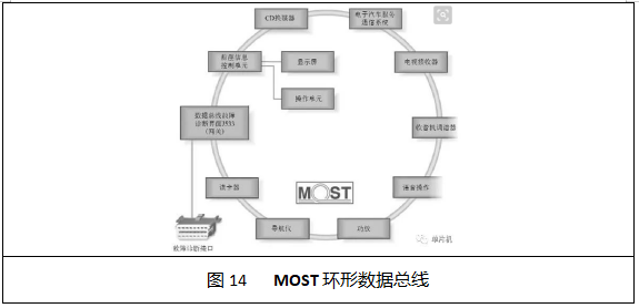
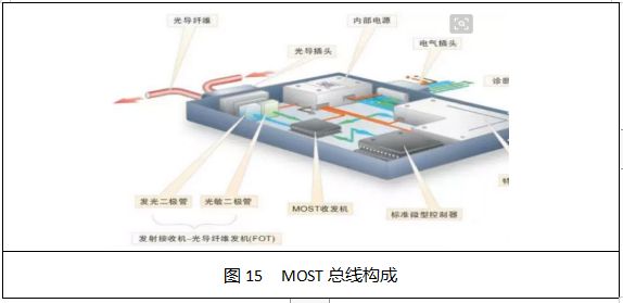
3. Structure of the MOST Bus The structure of the MOST bus is shown in Figure 15. (a) Fiber optic connectors: Optical fibers use specialized optical connectors to connect to control units. An arrow on the connector indicates the direction of the signal (to the receiver) at the input end, and the connector’s casing forms the connection with the control unit. Optical signals enter the control unit or are transmitted to the next bus user via optical fibers and connectors. (b) Control unit power module: The power sent from the electrical connector is distributed by an internal power supply to various components, allowing for the individual shutdown of certain components within the control unit to reduce static current. (c) Transceiver – fiber optic transmitter (FOT): This device consists of a photodiode and a light-emitting diode, with incoming optical signals converted into voltage signals by the photodiode and sent to the MOST transceiver. (d) MOST transceiver: The MOST transceiver consists of both a transmitter and a receiver. (e) Control unit (ECU): The control unit (ECU) contains a microprocessor for managing all basic functions of the control unit. (f) Dedicated components: These components are used to control specific functions, such as CD players and radio tuners.
-
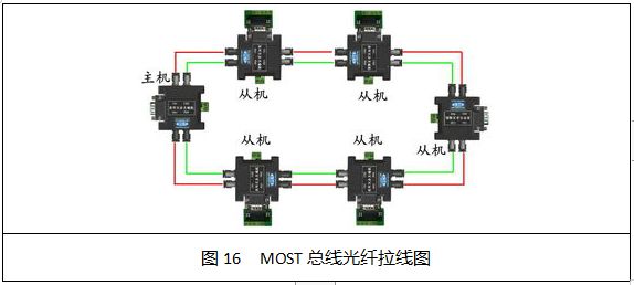
MOST Bus Fiber Optic Diagram
The MOST bus adopts a ring structure, transmitting data in one direction only within the ring bus. Each MOST control network allows for a maximum of 64 node connections (devices). MOST is fully compliant with the ISO/OSI seven-layer data communication protocol reference model, and for network connections, it uses a ring topology. However, for more stringent control applications, MOST also allows for star (also known as radial) or dual-ring connection configurations, as shown in Figure 16.
-
The MOST bus uses optical pulses to transmit data.
-
The transmission technology of MOST is similar to that of the Public Switched Telephone Network (PSTN), with defined data channels and control channels, where the control channel is used to set how to use and transmit data over the data channels.
Once set, the data will continuously flow from the sender to the receiver without further packet processing during the process, making this design mechanism most suitable for real-time audio and video streaming transmission. 5. Analysis and Summary (a) CAN, as a reliable automotive bus, has been widely applied and is currently the backbone network within vehicles. CAN is primarily used for data transmission in vehicle control systems and is the most widely used standard in active vehicular network applications, with a maximum transmission speed of 1 Mb/s. Initiated in the 1990s, the Controller Area Network (CAN) revolution has had a tremendous impact on the development of the entire automotive electronics industry. (b) LIN is a low-cost general-purpose serial bus primarily used in automotive applications such as door, sunroof, and seat controls, with a maximum transmission speed of 20 kb/s. (c) FlexRay is a new generation of automotive control bus technology following CAN and LIN, also belonging to shared bus technology, with a bandwidth of up to 10Mbps. The main advantage of FlexRay is its higher bandwidth compared to CAN, meeting the requirements of critical automotive applications; however, as shared bus technology, it is also costly, mainly suitable for drive-by-wire systems in mid to high-end vehicles (such as suspension control, transmission control, brake control, steering control, etc.). (d) MOST primarily supports multimedia streaming data transmission, with the MOST150 standard allowing for a maximum bandwidth of 150 Mb/s, widely used in in-vehicle multimedia data transmission applications. MOST150 supports IP-based applications, but due to single vendor issues, the basic development costs are relatively high. In summary, the automotive bus has evolved from twisted pairs to coaxial cables and now to fiber optics, indicating that automotive networks are a comprehensive network system.
-
In-Vehicle Ethernet Technology
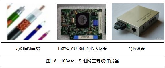
The development of intelligent connected vehicles calls for support from in-vehicle Ethernet technology. With the support of in-vehicle Ethernet, the development of intelligent connected vehicles is also inevitable. Recently, the IEEE released standards for in-vehicle Ethernet, which will be one of the important technologies driving the realization of the Internet of Vehicles. In-vehicle Ethernet not only meets the bandwidth requirements for applications such as ADAS, audio-visual entertainment, and automotive connectivity but also possesses the potential to support higher performance in the future (such as the larger data transmission required in the era of autonomous driving). It will become the cornerstone for achieving multi-faceted high-speed communication. 1. Introduction to In-Vehicle Ethernet Ethernet refers to the baseband local area network specification created by Xerox and jointly developed by Xerox, Intel, and DEC, with the general Ethernet standard introduced on September 30, 1980. It is the most commonly used communication protocol standard for existing local area networks. Ethernet uses CSMA/CD (Carrier Sense Multiple Access with Collision Detection) technology and operates at various types of cables at a rate of 10M/S. Ethernet is similar to the IEEE802.3 series standards, including standard Ethernet (10Mbit/s), Fast Ethernet (100Mbit/s), and 10G Ethernet (10Gbit/s), all complying with IEEE 802.3. In-vehicle Ethernet is based on the currently mature Ethernet technology, which can well meet the new demands of automotive electronics and provide reliable, mature, low-cost, and standardized solutions, with broad development prospects in vehicles in the future. 2. Advantages of In-Vehicle Ethernet (a) High bandwidth at low cost. New automotive features, such as automatic parking systems, lane departure detection systems, blind spot detection, and advanced infotainment systems, have led to a demand for new data buses. Ethernet seems to provide a comprehensive solution for these needs. For example, Broadcom’s breakthrough BroadR-Reach technology can transmit signals using a single pair of unshielded twisted pairs, providing broadband performance of 100Mbit/s and higher, while reducing cable weight by 30% and cutting connection costs by up to 80%. (b) Support for multiple protocols for different applications. Traditional in-vehicle networks support relatively single communication protocols, while in-vehicle Ethernet can simultaneously support multiple protocols or application forms, such as AVB, TCP/IP, DOIP, SONIP, etc. Ethernet AVB is an extension of traditional Ethernet functions, enhancing the real-time capabilities of traditional Ethernet audio and video transmission by adding precise clock synchronization and bandwidth reservation protocols, making it a highly promising technology for real-time network audio and video transmission. SOME/IP (Scalable Service-Oriented Middleware on IP) specifies the video communication interface requirements for in-vehicle camera applications, applicable in the field of in-vehicle cameras and enabling mode control for driving assistance cameras through APIs. (c) Ethernet is a continuously updatable and developing technology. After the rapid development of standard Ethernet (10Mbps), Fast Ethernet (100Mbps), and Gigabit Ethernet, Ethernet continues to undergo iterative upgrades. While continuously supporting bandwidth growth, it also maintains compatibility with existing systems. Therefore, once Ethernet technology is promoted in the automotive industry, it will bring not only a mature communication technology but also an adaptability for the future. 3. Ethernet Network Standards IEEE802.3 defines the contents of the physical layer wiring, electrical signals, and media access layer protocols. Ethernet is currently the most widely used local area network technology, largely replacing other local area network standards, such as token ring, FDDI, and ARCNET. After the rapid development of 100M Ethernet at the end of the 20th century, Gigabit Ethernet and even 10G Ethernet are continuously expanding their application scope under the promotion of international organizations and leading enterprises. Common 802.3 applications include: (a) 10M: 10base-T copper wire UTP mode). 10Base-5 uses a 0.4-inch diameter, 50Ω impedance coarse coaxial cable, also known as thick Ethernet, with a maximum segment length of 500m. It uses baseband transmission methods and has a bus topology. The main hardware devices for 10Base-5 networking include thick coaxial cables, Ethernet cards with AUI ports, repeaters, transceivers, transceiver cables, terminators, etc., as shown in Figure 18.
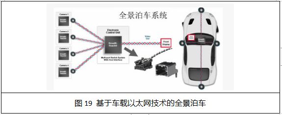
(b) 100M: 100base-TX (copper wire UTP mode); (c) 100base-FX (fiber optic); (d) 1000M: 1000base-T (copper wire UTP mode). 4. In-Vehicle Application Examples Examples of panoramic parking based on in-vehicle Ethernet technology, as shown in Figure 19, indicate that in-vehicle Ethernet has already integrated wireless communication capabilities.
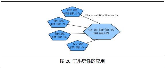
6. Development Trends of In-Vehicle Ethernet (a) Subsystem-level applications, as shown in Figure 20.
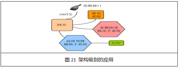
(b) Architecture-level applications, as shown in Figure 21.
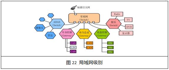
(c) Local area network-level applications, as shown in Figure 20.
The development of intelligent connected vehicles calls for support from in-vehicle Ethernet technology, making the advancement of intelligent connected vehicles inevitable.
How to Find Me
1. Click the blue text at the top Shenzhen Automotive Electronics Industry Association to follow in one click;
2. Search for the WeChat public account: “Shenzhen Automotive Electronics Industry Association” or “qidianxiehui”;
3. Scan the QR code to follow