Abstract: This paper proposes a design method and specific implementation plan for a control system based on dual STM32 chips. The control system uses two STM32F107VCT6 chips as master and slave controllers, communicating via a high-speed SPI interface to ensure real-time performance during the control phase. The hardware layout of the system is introduced, and the software design process of the embedded system is provided. Experimental results demonstrate that the overall system performs excellently, providing a reliable operating platform for subsequent complex control computations.
1 System Hardware Design
1.1 System Function Division and Hardware Layout
The autonomous flight control system of a multirotor UAV is quite complex and generally requires the design of three types of controllers: position controller, speed controller, and attitude controller. Additionally, algorithms for attitude angle estimation and navigation data fusion are also needed.
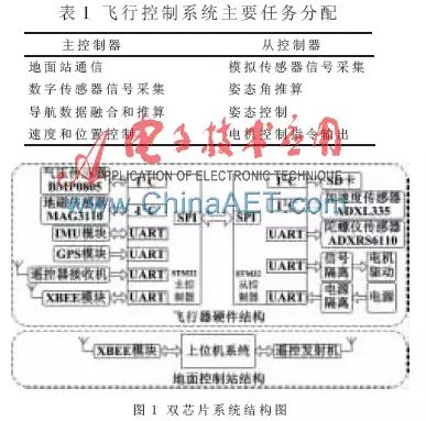
To meet the above control and algorithm requirements, the hardware layout of the onboard part is particularly important. To achieve good real-time control performance, the control frequency is a significant consideration. Therefore, to carry out high-frequency control computations, this paper designs a dual-chip control system, where two processors handle data simultaneously and coordinate to achieve autonomous flight. The allocation of cooperative tasks is shown in Table 1. The structure of the dual-chip system is illustrated in Figure 1. The master controller includes an IMU module, GPS module, remote control wireless receiver, and XBEE wireless transmission module; the slave controller includes a gyroscope sensor, three-axis accelerometer, geomagnetic sensor, barometric pressure sensor, PWM output module, and SD card data storage.
1.2 System Hardware Selection
(1) Master and Slave Controllers: The ST company’s STM32F107VCT6 model 32-bit microprocessor is used, with a clock frequency of up to 72 MHz, ensuring the stability and real-time performance of the UAV control system with its rich hardware interface resources and powerful DMA control method. The master-slave CPUs communicate via a SPI interface with a speed of up to 18 MHz. For practical applications, hardware handshaking is added to the communication interface, where the master queries the slave’s status before transmitting data; if ready, it begins to send data. This avoids data loss when the master sends data while the slave is in the process of receiving configuration codes and cannot receive data correctly.
(2) Analog Sensors: Accelerometer (ADXL335), gyroscope sensor (ADXRS610). The advantage of using analog sensors is that they can collect data at high frequencies and accurately, meeting the 400 Hz attitude control frequency requirement.
(3) Digital Sensors: Magnetometer (MAG3110), barometer (BMP0805), GPS module. Digital sensors are relatively simple to use and have lower frequency requirements when controlling position and speed, thus meeting the requirements.
(4) Wireless Transmission Modules: Remote control, remote control receiver, XBEE wireless transmission module.
(5) Expansion Module: IMU module. High-performance IMU modules can be used to verify the performance of various sensors on the control board and estimate the accuracy of the estimated attitude angles.
2 Embedded System Software Design
The system software is developed based on the IAR software platform, using a mix of assembly language and C language programming. It is mainly divided into software design for the master controller and slave controller.
2.1 Master Controller Software Design
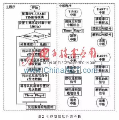
The software flowchart for the master controller is shown in Figure 2. The data reception from the remote control, data reception from the host computer, GPS data reading, altimeter and magnetometer data reading, and main loop control frequency are all completed using interrupt programs. To reduce the CPU load, DMA functionality is used for ground station data output, requiring no CPU intervention.
2.2 Slave Controller Software Design
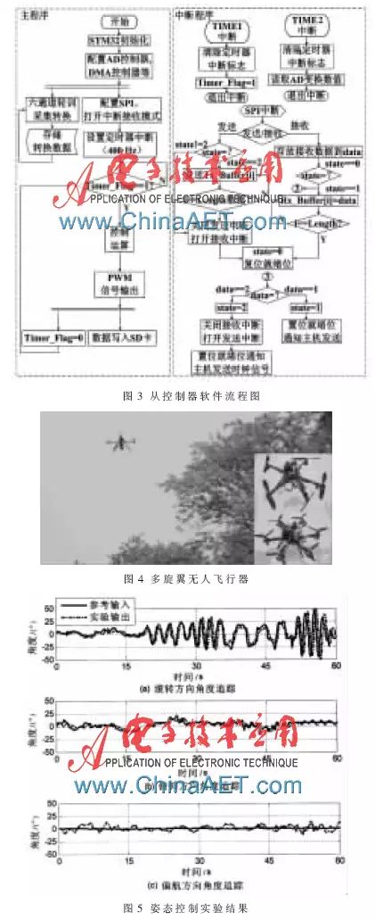
The slave controller needs to perform 400 Hz control computations and also requires separate configurations for the STM32’s USART interface, SPI interface, and timer interrupts. The sampling frequency is set to 2000 Hz, and the collected data undergoes Butterworth digital low-pass filtering. The Butterworth digital filter has the characteristic of maximum flat amplitude within the passband and a gradually declining response to zero in the stopband compared to other digital filters. The performance indicators of the filter are as follows: passband cutoff frequency 20 Hz, stopband cutoff frequency 100 Hz, minimum attenuation in the stopband 20 dB, maximum attenuation in the passband 3 dB. For SD card data writing, SPI’s DMA functionality is also used to achieve fast data writing, saving CPU time.
The software flowchart for the slave controller is shown in Figure 3, where receiving and sending data to the master and the main loop frequency are completed using interrupt programs. Additionally, to save CPU time for reading and writing peripheral devices, the ADC’s DMA functionality is used to read data from the analog sensors, delegating data collection and storage to the DMA controller.
3 Experimental Results
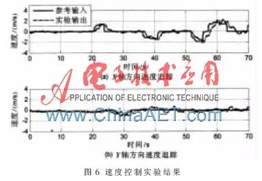
To verify the feasibility of the system plan, a flight control system containing speed control and attitude control was mounted on a quadrotor UAV for outdoor flight experiments, as shown in Figure 4.
Figures 5 and 6 show that the controller can effectively track speed target values, allowing the UAV to fly at the desired speed. Thus, it can be concluded that the entire system exhibits good target tracking and stability.
This paper presents a novel design scheme for a multirotor UAV control system using a dual-chip structure. The design and implementation process is detailed from both hardware and software perspectives, with different controllers designed for the master and slave units. Experimental results indicate that the system has high stability, can complete various data transmission methods, has fast processing speeds, and effectively meets the computational requirements for autonomous flight, laying a solid foundation for achieving autonomous flight of such UAVs.
However, this is indeed a profession with a wide employment scope, with countless paths for career transition.