The charging system is an important foundational support system for new energy vehicles and is a key condition for the industrialization and popularization of new energy vehicles, significantly impacting its industrial development.
Currently, the charging modes are divided into AC and DC. New energy vehicles that support AC mode are equipped with on-board AC-DC converters and can simply use AC chargers to supply single-phase 220V or three-phase 380V for electric vehicle charging. This mode has a lower output power and longer charging time. The DC mode uses DC chargers to provide DC voltage/current to the power battery of new energy vehicles. The charger (hereinafter referred to as “DCCharger”) needs to communicate with the on-board battery management system (hereinafter referred to as “BMS”) to obtain battery information and charging information. This charging method has a higher output power and shorter charging time.
According to the requirements of the communication protocol between non-vehicle conductive chargers and battery management systems for electric vehicles, GBT 27930—2015, hereinafter referred to as “national standard”, when developing the DC charging function of BMS, since the DCCharger needs to communicate with BMS via CAN, the interaction logic is complex and involves J1939 long frame protocol messages, which have very high real-time requirements. General CAN devices are often unable to meet these requirements. Therefore, a dedicated simulation DCCharger is needed to interact with BMS and to inject faults that may occur in the DCCharger to assist in BMS development.
The “National Standard DC Charging Simulation System” independently developed by Shanghai Tongzhan New Energy Technology Co., Ltd. has the following system structure as shown in the figure below.
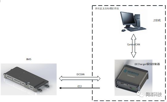
It has the following functions:
1. Strictly follows the national standard, interacts with BMS through CAN message exchange, simulating the four normal charging phases of “handshake”, “configuration”, “charging”, and “charging completed”.
2. Can simulate timeout faults of various messages from DCCharger and enter the corresponding abnormal charging termination process.
3. Can respond to the charging termination messages sent by BMS and enter the corresponding abnormal termination charging process.
4. Can inject faults from the following list:
|
Item |
Type |
|
Message CRM_0x00 |
Message send timeout |
|
Message CRM_0xAA |
Message send timeout |
|
Messages CTS and CML |
Message send timeout |
|
Message CRO |
Message send timeout |
|
Message CCS |
Message send timeout |
|
Message CSD |
Message send timeout |
|
Illegal message fault injection |
|
|
Illegal charging sequence fault injection |
|
|
CC2 fault injection |
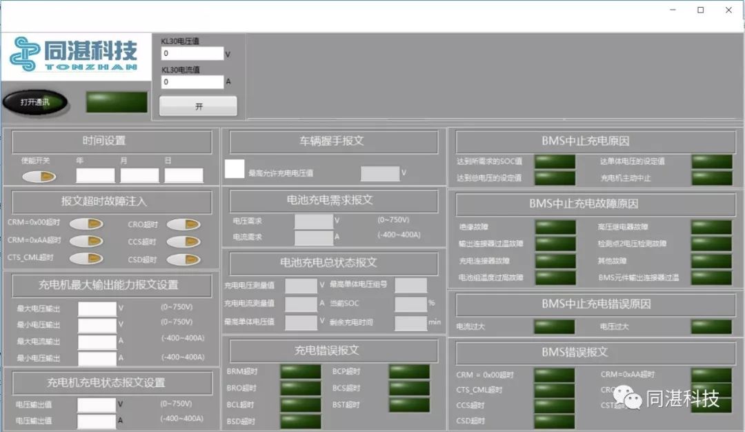
5. The equipped upper computer can set the time in the message (CTS), the maximum and minimum voltage and current in the message (CML), and the voltage and current output values in the message (CCS).
6. The equipped upper computer can display the maximum allowable total voltage value in the message (BHM), the voltage and current demand values in the message (BCL), the charging mode, the charging voltage and current measurement values in the message (BCS), the current SOC, the maximum single battery voltage and group number, estimate the remaining charging time, the reason for charging termination in the message (BST), and the fault reason for charging termination in the message (BEM) for the timeout items received by BMS, as well as the timeout items received by the charging pile in the message (CEM).
7. Can provide the circuit interface for CC2.
Upper computer interface
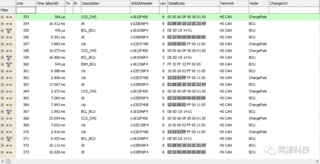
DC charging interaction messages
The system supports customized development according to customer requirements. We welcome everyone to consult. For more details, please click:
http://www.tonzhan.com/
https://shop125639435.taobao.com/spm=2013.1.1000126.2.4fa67c6f0d1kKv