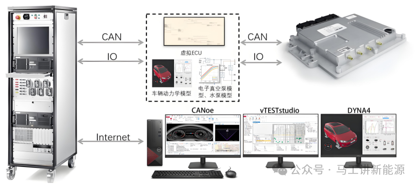
In HIL testing, fault injection is a commonly used testing method, typically implemented using fault injection modules to simulate electrical faults, such as short circuits, open circuits, etc. The principle of fault injection is to introduce signal faults between the tested ECU and other parts of the system, such as voltage fluctuations, ground short circuits, or open circuits, to simulate various issues that may occur during actual operation. For example, by placing the fault injection module (FIU) between the I/O interface and the ECU, it can simulate faults like ground short circuits or open circuits.
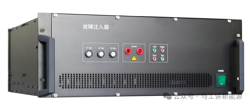
Taking the fault injection board as an example, here are the specific faults that can be simulated during testing:
1. Open Circuit Fault Simulation:
– The fault injection board can simulate open or interruption faults by disconnecting the corresponding relay, testing the ECU behavior after the signal is interrupted.
2. Ground Short Circuit or Power Short Circuit Simulation:
– The fault injection board can configure a fault bus to simulate power lines, system grounding, or other power sources in the system, thus simulating ground or power short circuits.
3. Pin-to-Pin Short Circuit Simulation:
– The fault injection board can connect the signal lines of the ECU to one or more other signal lines to simulate pin-to-pin short circuit faults.
4. Channel Configuration:
– Each channel of the fault injection board can simulate fault states such as power short circuits, ground short circuits, open circuit faults, and short circuits between any two pins.
5. Fault Bus Topology:
– In the fault bus topology, each FIU channel consists of 3 single-pole single-throw (SPST) relays to control the channel’s state.
6. Software Control:
– The fault injection board is typically controlled by upper-level software, which is easy to operate and supports automated testing by sending commands to the microcontroller (MCU) on the board through RS232. The MCU controls the relay actions based on the commands to execute the corresponding fault modes.
7. Current Carrying Capacity:
– Each channel of the fault injection board can provide a sustained current of up to about 10A during fault conditions to simulate different fault scenarios.
8. Flexibility of Fault Modes:
– The fault injection board can be flexibly configured according to testing needs to simulate various electrical faults, such as corrosion, short circuits/ open circuits, etc.
Through the methods mentioned above, the fault injection board can effectively simulate various electrical faults in the HiL testing system to test and verify the ECU under different fault conditions.