


Abstract
Electromagnetic Fault Injection (EMFI) is a well-known method for introducing faults for the security analysis of digital devices. Such faults can be viewed as similar to those known to occur naturally in digital devices, which is a recognized issue in designing safety-critical systems.
Many standards have been established for safety-critical systems, including those for increasing the natural fault occurrence rate using particle sources. In this work, we demonstrate that desktop EMFI tools can be used to perform similar tests, effectively accelerating the assessment process.
We illustrate the use of EMFI tools for security assessments to reproduce well-known security problems present in automotive ECUs—issues that cannot be easily reproduced using other techniques.
1. Introduction
Fault injection allows attackers to modify the operation of the device under test. These attacks may include simple control flow changes that allow bypassing the secure boot process, as well as differential fault analysis attacks that enable recovery of cryptographic materials.
To understand the capabilities of an attacker, defenders often assume some fault model that demonstrates the attacker’s capabilities. These can be simple—such as assuming the attacker can “skip instructions”—or more complex—such as the attacker being able to flip single or multiple bits. This may include treating specific bits as part of control flow hijacking or other advanced attacks.
These faults are introduced through various methods—manipulating external clocks or voltage supplies is a simple way to introduce faults, but there are also other methods, including optical faults caused by flash tubes or lasers, or electromagnetic faults.
These attacker models typically assume that the attacker can trigger faults in a timely manner at specific instances. This ability to trigger faults at specific moments defines the difference between faults with specific security implications and those that may occur naturally due to failures or errors in computer systems.
Random faults in computer systems are a well-known issue, historically addressed in systems requiring better long-term stability with solutions like error-correcting code memory. With a long history of safety-critical design processes, we can explore the fault models used in safety-critical systems to better understand where safety and security fault models overlap.
This work will look at a typical automotive product example that faces concerns about safety-critical design failures. Despite considerable efforts, this failure has previously only been partially captured through classical safety-critical design assessment tools. By applying tools commonly used in safety analysis, we will demonstrate how to reproduce this failure.
The specific contributions of this work are:
1) The connection between fault injection in safety and automotive safety testing
2) Static damage to SRAM using EMFI
3) Reproducing safety-critical vulnerabilities using EMFI
This paper will first introduce the standards used in safety-critical systems in Section 2, including a discussion of how these standards have been reported in similar safety-focused articles previously. Based on prior work in functional safety and cybersecurity, Section 3 will show specific links to common metrics used to assess whether SRAM memory is damaged. Then, we will demonstrate an “attack” on production ECUs in Section 4 to reproduce safety-critical vulnerabilities, followed by a discussion of conclusions and future opportunities in Section 5.
2. ISO 26262-11 Faults and Failure Modes
The safety-critical design of digital systems is well-known in many industrial systems. This paper focuses on automotive systems, particularly the ISO 26262 series of standards, which is an adaptation of IEC 61508 for automotive systems.
ISO 26262 consists of several parts. Of particular interest are Part 11 (“ISO 26262 Guidelines for the Application of Semiconductors”), Part 5 (“Product Development at the Hardware Level”), and Part 6 (“Product Development at the Software Level”).
ISO 26262-11 defines example faults and failure modes for various types of digital devices. Three of these directly resemble safety fault models: “Fault Model for Non-Memory Digital Components (5.1.2)”, “Detailed Fault Model for Memory (5.1.3)”, and “Failure Modes for Digital Components (5.1.4)”. The following information in the remainder of this section is defined in ISO 26262-11 but is recreated here for quick reference.
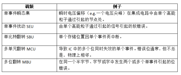
Section 5.1.2 of ISO 26262-11 defines transient faults for non-memory digital components, as shown in Table 1. From this definition, we can see that Single Event Transients (SET) can lead to various types of interference depending on the structure of the transient interaction. Note that this definition of non-memory digital components may still include memory, such as registers in a CPU, but later in Section 5.1.3 of ISO 26262-11, independent memory devices (e.g., FLASH or SRAM memory) cover other fault modes, such as being “stuck at 0” faults.
Transient faults in memories like SRAM are well-known and follow the general format of Table 1. A major addition is the Single Event Latch-up (SEL) fault model, which is typically detected through constant higher current consumption to the target device. Such assessments have been conducted from a “safety” perspective using laser fault injection techniques on various devices, including work on newer devices like Kintex-7 FPGAs.
These safety standards distinguish between fault modes and failure modes. A given fault may lead to one of the failure modes (FM) listed in Table 2. These apply to general digital devices performing certain given functions. This function varies based on the device and the area of the device considered. A CPU may have the overall function of executing instructions but may also have specific functions, such as interrupt handling or internal memory access functionality. The failure of a given function using the failure modes in Table 2 will yield us the specific function’s failure.
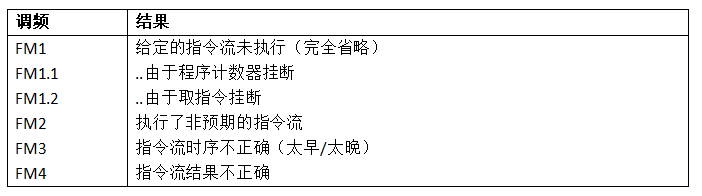
For example, a CPU will have the functionality of “executing a given instruction stream based on a given instruction set architecture”. The failure modes in Table 2 may lead to failures in Table 3.
These failures follow the well-known instruction fault models typically found in safety-oriented fault injection. For example, the typical “instruction skip” fault model is included in FM1 but may also be part of FM2 and FM3. Incorrect branching can be seen as FM4, while instruction mutations are covered by FM2.
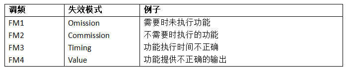
Table 2: ISO 26262-11 Failure Modes
When comparing tools and techniques for developers using safety tools, this mapping is particularly useful. While safety fault injection has a specific timing, the fact that safety-critical systems cannot be assumed to be robust against motivated attackers suggests that the underlying fault models themselves are consistent. We will now explore how tools typically used for safety analysis can be utilized as part of safety-critical failure simulation.
3. Electromagnetic Fault Injection
The goal of Electromagnetic Fault Injection (EMFI) is ultimately to inject voltage into the structure of the chip itself—this can lead to “soft error” faults (e.g., bit flips in registers or SRAM) or temporary erroneous voltage levels during reads (a SET). The fact that strong fields have the ability to disrupt data (without damaging the device) has been known since at least the 1970s.
While EMFI is typically used for security testing purposes, the fault injection process in security testing more generally follows the JESD89A standard (a reference for testing devices for “soft errors”), which uses alpha particle sources to accelerate soft errors. Since these alpha particle sources are not easily installed on desktops, using standard EMFI tools to achieve similar results would be a valuable practice. We will next demonstrate how static RAM memory damage can be recreated using desktop EMFI equipment.
A. Memory Damage Caused by EMFI
Previous research on EMFI has indicated that errors occur only during transmission, and static damage has not been observed. This would be a significant distinction, as most safety-critical testing of storage devices assumes that charged particles cause unit or multi-bit faults. To help validate the connection between safety and security testing, we will demonstrate that static bit flips can be achieved using EMFI, consistent with assumptions widely used as part of safety-critical testing.
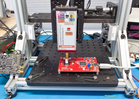
The tests will be conducted using a ready-made target board called ballistic gel (part of the ChipSHOUTER project). This target has a 32 Mbit SRAM chip that can be used to understand how bit flips vary with different settings. By downloading patterns to the device, injecting faults, and observing the locations of pattern flips, we can understand what types of impacts may arise. The physical board is mounted on the test platform shown in Figure 1.
When performing EMFI injections, we can adjust several characteristics. First is the design of the injector itself, for which protocols have been proposed to aid comparison across devices. In this work, we will use a single EMFI platform, ChipSHOUTER. We will compare the effects of changing the injector tip (coil) details and the charging voltage.
B. The Effect of Tip Size and Voltage
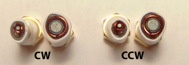
The accompanying injector tips vary in size with ferrite magnetic cores and the winding direction around the core: two 4mm tips and two 1mm tips, each with “clockwise” (CW) and “counterclockwise” (CCW) versions. The expected exchange of positive and negative pulse polarities corresponds to changing the winding direction. However, for safety reasons, changing the winding direction ensures that the maximum voltage is not at the most exposed end of the winding. Examples of various coils are shown in Figure 2.
Comparing the effects of varying charging voltage indicates a clear relationship between pulse voltage and the number of damaged bytes. Increasing the charging voltage increases the number of flipped bytes.
Using the 4mm probe tip, there was no significant difference in the number of damaged bytes between clockwise (CW) and counterclockwise (CCW) winding directions in each fault injection attempt. This may lead to some deviations in bit setting or bit resetting faults, but generally, this is not a concern for safety testing.
Results from the 1mm core tips seem to differ from those of the 4mm core tips. Here, CW and CCW tips appear to have different responses. This is likely due to physical structural tolerances—the length of the tips themselves varies slightly, resulting in different heights above the chip surface. Note that this does indicate a potential for a small number of byte errors. The 1mm CW tip in this configuration shows 1–10 byte errors at charging voltages below 280V.

C. The Effect of Height
The physical height of the injection tip is expected to affect the number of bit flips. In the following example, we will keep the charging voltage fixed at 200V and use the 1mm CCW tip. The tip will be raised from the chip surface, and faults will be repeated 100 times. This allows us to evaluate the repeatability of height variations. The results are shown in Figure 4.
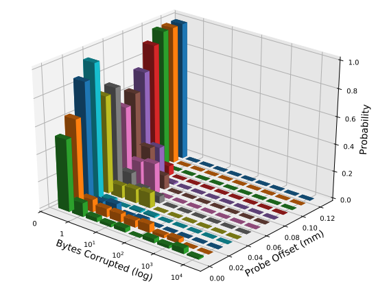
Moving the probe away from the surface shows a reduction in faults, but as shown in the figure, there is still considerable randomness in the process. It is recommended to lean towards zero when the probe is moved away, but occasionally a significant number of flips at the same location may occur.
D. XY Scanning Positions
Scanning the EMFI positions on the chip surface not only affects the location of injected faults but also, due to different characteristics in the device, affects the quantity. For example, scanning the same faults on top of SRAM yields the results shown in Figure 5. Note that several areas have a 1-byte fault, some areas have more than 1-byte faults (but not the large number of faults seen previously), while other areas have a large number of faults.
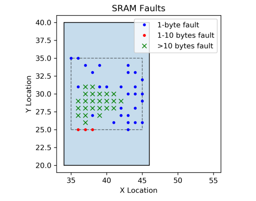
This indicates that several different variables affect the types of faults generated by the EMFI platform. This can be used to target different types of faults needed for safety testing, such as faults that affect small portions and large portions of the device simultaneously.
4. Using EMFI for Security Testing
As shown in the previous section, EMFI can inject faults similar to those that systems designed to operate in safety-critical environments should be protected against. The focus of this work is automotive systems, where we can compare the results of the systems with issues suspected to arise from random bit flips.
The example target will be an ECU from a 2006 model year. This relatively older ECU was chosen because existing public work discusses the possibility of software failures occurring without triggering expected fail-safe behavior. Since most production ECUs are not available for code inspection, the presence of expert witness testimony is particularly interesting, as it allows us to understand what potential flaws experts believe exist in the system.
According to expert witness testimony, the fail-safe logic used in the ECU does not detect certain memory corruption events. This would lead to unintended vehicle operations, particularly the decoupling of the vehicle throttle from the requested user input. Notably, this seems to suggest the throttle “sticking” in one position but not fully opening. This has been validated through the test platform, where specific bits flipped in a full ECU on a running vehicle. Testimony in the trial indicated that drivers who experienced potential defects described the throttle entering full open (throttle fully open) position before sticking. This indicates a difference from the root cause identified through code analysis, but as noted by the expert witness, it is difficult to cover all potential defects.
Recent studies on these devices have shown that voltage fluctuations can temporarily lead to full throttle open, but do not cause the throttle to stick. However, this does suggest that some combination of voltage fluctuations and memory corruption may lead to an overall erroneous situation, but the practicality of this remains in question—can the damage type from random particles or EMFI explain both?
Using EMFI, we can demonstrate that memory corruption can lead to excessive power consumption, explaining the possibility of both faults existing simultaneously. This result, previously undetectable using classical static or dynamic analysis tools, will be completed in a black-box manner, without any modifications to the actual ECU or sensors. However, the authors must emphasize that the following safety tests were not performed on the entire system—i.e., safety testing did not show overall system failures, as other fault protection measures were not studied in this example. If testers do have knowledge of the system under test, more advanced analyses can be performed—for example, comparing memory and register dumps to understand where the damage was inserted.
A. Test Bench
To perform the safety check, we need to operate the system within some normal ranges. In this case, a very simple engine/vehicle simulator was built around the ECU to allow the system to operate normally.
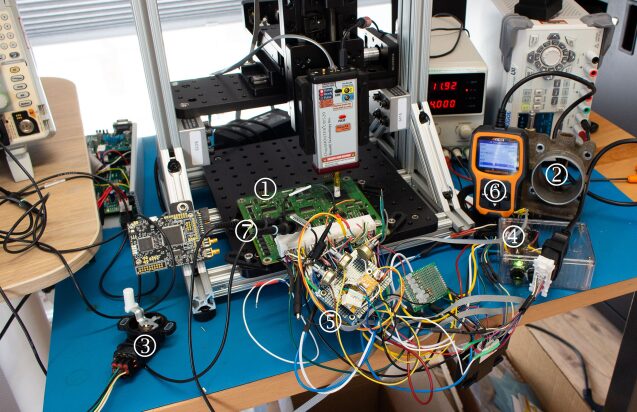
The test bench is shown in Figure 6, which includes the following items:
1) The main ECU board we are testing.
2) The physical throttle body connected to the ECU.
3) The throttle pedal sensor connected to the ECU.
4) An ignition switch (turning power on/off like a key).
5) A simulator providing cam and crank signals.
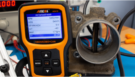
6) A diagnostic reader for monitoring ECU data streams.
7) A probe monitoring the signals driving the throttle body.
8) The ChipSHOUTER providing EMFI tools.
9) An XYZ platform allowing scanning with the EMFI tool.
The current setup does not automatically monitor outputs but uses human-in-the-loop to observe patterns outside specifications (e.g., mismatch between throttle position and commanded position).
B. EMFI Results
Operating the device while performing EMFI noted several failure modes, including:
1) The ECU reset and continued running.
2) The ECU entered fail-safe mode, such as reducing throttle opening.
3) The throttle motor drive signal ceased normal operation.
The final failure mode is the most interesting, as it appears the control loop is closed (position typically follows the pedal). The motor is driven by a pulse width modulation (PWM) signal, with the comparison of the two PWM modes shown in Figure 7.
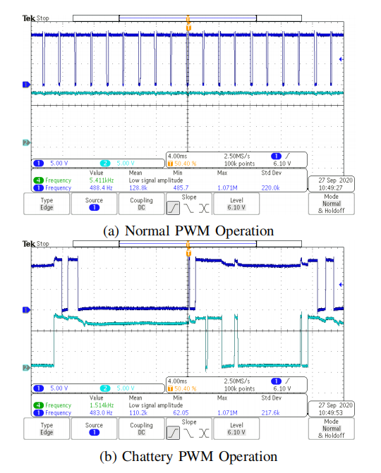
While the throttle body appears to remain at the requested position, it now exhibits noticeable “tremors”. Additionally, power consumption surged from a normal 1.6A to 3-5A (current consumption became less stable). This sudden jump in current consumption would cause additional voltage drops on the ECU power rail, which is consistent with previous work showing full throttle open states during voltage fluctuations.
1) Throttle Sticking Result: Once in the wrong PWM mode, the throttle ultimately becomes fully closed or fully open, with changes in the throttle pedal sensor no longer affecting the throttle position. In this case, current consumption further increases, and the PWM waveform is clearly observed, with the output signal now constant. After entering this mode, a power reset is needed to exit this mode.
In this mode, the ECU continues to provide ignition output signals in response to changes in cam and crank signals, and the OBD-II scanning tool continues to provide diagnostic information. A photo of the throttle stuck open is shown in Figure 8. Note that the throttle shown here is commanded to open 88%. During normal operation, the maximum throttle opening on the test bench was only 81%, so the commanded 88% throttle position here seems to exceed normal operating values.
5. Conclusion
The possibility of memory corruption or other failures is a well-known issue in safety-critical design, and referencing issues like electromagnetic fields leading to memory corruption before using these attributes in safety assessments is crucial. There is a wealth of knowledge surrounding the design of safety-critical systems like automotive devices, which is often separated from the knowledge obtained and applied, focusing on the safety analysis of automotive systems.
Previous work has indicated that EMFI can be used for safety analysis, such as bypassing passwords or executing differential fault analysis. In this work, we demonstrate that EMFI can also be part of safety assessments by showing that typical error types expected to be randomly generated by charged particles can also be produced using EMFI.
Furthermore, the “black box” attack types commonly used in security assessments have also been utilized to reproduce elusive vulnerabilities in automotive ECUs. This indicates that both functional safety and cybersecurity engineering have the capability to learn useful tools and techniques from each other’s domains.

🎁Free trial application for REANA network security analysis tools, scan the code to add Niu Xiaoka’s corporate WeChat, reply “REANA”

🎁Free trial application for software static and dynamic code testing tools, scan the code to add Niu Xiaoka’s corporate WeChat, reply “Software Testing”

Automotive Safety Premium Services

For more industry news, technical interpretations, and inquiries, please visit the official website of Niu Ka: i-newcar.com
[Functional Safety] ISO 26262 SEooC Compliance Based on ROS Architecture
[Automotive Safety] Synergy Between Functional Safety and Cybersecurity for Autonomous Vehicles
[Functional Safety] Functional Safety System Requirements Analysis and Design for Electric Vehicle Charging Infrastructure
[SOTIF] How to Reduce the Workload of Scenario-Based Safety Analysis for Autonomous Driving
[Automotive Safety] Machine Learning Security Solutions for Autonomous Vehicles
[Cybersecurity] Addressing Cybersecurity Issues in Next-Generation Mobility Ecosystems
[SOTIF] Scenario-Based Expected Functional Safety Assessment Framework for Autonomous Vehicles
[Automotive Chips] Enhancing Critical System Security with SoC and MCU Combined Approaches
[Automotive Chips] Validating SPI Security Architecture through FMEDA Fault Injection
Safety Strategy for Autonomous Vehicle Platooning Based on ISO/PAS 21448 Standards
Automotive Software Quality Management Integrating ASPICE, ISO 26262, ISO 21448, and ISO 21434
Design and Implementation Process of Advanced Driver Assistance Systems Based on Open Source AUTOSAR
Meeting Automotive Functional Safety Requirements with GPIO
Step-by-Step Guide to FMEDA for Beginners
Estimating Basic Failure Rates for Semiconductor Functional Safety Using IEC62380 and SN29500