
Jiang Yan
(Qinghai-Tibet Railway Company, Xining Signal Section, Xining 810006)
Abstract: In the process of system analysis, simulation testing methods are widely used, among which the fault injection method is an effective testing and verification means. This paper mainly studies the simulation fault injection method and its application in the electromagnetic compatibility (EMC) of train operation control systems. First, it introduces a High Level Architecture (HLA) based simulation platform for train operation control systems. Based on this simulation platform, a Markov chain based EMC fault analysis method is proposed, and an EMC fault case database is established. Combining typical EMC faults in the train control system, corresponding fault testing cases are established, tested on the train control simulation platform, and safety analysis results and fault statistical characteristics of the train control system are obtained. Experimental results show that the fault injection method can effectively assess and analyze the EMC fault characteristics of the train control system.
Keywords: fault injection; train control system; EMC; HLA; Markov
DOI: 10.3969/j.issn.1673-4440.2017.02.019
The fault injection method is a system verification method that deliberately introduces faults into the tested system to check for faults within the system and their subsequent targeted behavior. In system analysis, fault injection, as an effective testing and verification means, has been widely applied across various fields with in-depth research. Currently, fault injection methods are mainly applied in three research areas: software-based fault injection research, hardware-based fault injection research, and simulation-based fault injection research. The fault injection method plays an important role in verifying system functionality, safety, and other aspects.
The hardware-based fault injection method mainly includes probe methods and insertion methods, focusing on fault injection at the pins of hardware chips to achieve system testing and verification. Software-based fault injection is mainly applied in software testing, including program mutation testing methods and seeding models for estimating the number of errors in programs. Compared to hardware-based fault injection methods, software-based fault injection methods do not damage the target system, allowing for easy program modification, execution, and statistical analysis of result data.
Railways have the characteristics of large transport capacity and stringent safety requirements, with the train operation control system being the core of ensuring train operation safety, often referred to as the “nerve center” of the railway. Currently, China adopts the CTCS train operation control system, which meets the technical specifications for different line transport needs in a hierarchical manner, with main features as shown in Table 1.

Since the train operation control system is developed to ensure transport safety, its primary mission is to guarantee safe train operation. The CTCS mainly consists of onboard subsystems and ground subsystems. However, the train operation control system includes various high-voltage and low-voltage devices, with different devices operating in relatively closed environments, making it susceptible to electromagnetic compatibility (EMC) faults. Once an EMC fault occurs in the control system, it may lead to serious train safety accidents. To ensure safe and reliable train operation, it is essential to analyze the electromagnetic compatibility characteristics of the train operation control system, making the dynamic EMC characteristic testing and analysis of the train control system imperative.
This paper first introduces the fault injection method based on simulation and the reasons for adopting this method, then discusses the functional composition of the train operation control simulation platform based on High Level Architecture (HLA), the design and implementation of the fault injection simulation module, and the establishment of fault case data. It proposes a Markov-based electromagnetic compatibility fault analysis method and finally analyzes the effectiveness of the fault injection method through specific fault cases on typical devices, along with statistical data of the results.
1 Simulation Method Based on Fault Injection
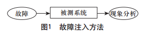
Some faults in the system are incidental or may occur after a period under certain conditions, making it difficult to observe and analyze the causes of faults and their subsequent consequences in real-time. As shown in Figure 1, the fault injection method is a technique that deliberately injects faults into the tested system to “create” the corresponding environment that causes faults or accelerates their occurrence, allowing system designers to observe and analyze fault phenomena in a timely manner and conduct corresponding evaluations. Therefore, fault injection is an effective testing method for evaluating fault tolerance mechanisms. The main difference between the fault injection method and existing testing and verification methods is that the fault injection method begins system analysis from a “faulty” state, while other testing and verification methods start from a “normal” system state.
Simulation-based fault injection is a convenient and effective method in fault injection, testing faults in the tested system in a simulated environment. Since the tested system operates in a simulated state, fault injection does not cause actual damage to the system, and the simulated environment facilitates fault injection, making it easier to modify the simulation environment, which is more conducive to fault injection, observation, analysis, and related data statistics, analysis, and verification. Therefore, fault injection is widely used in system testing analysis and verification.
Electromagnetic compatibility (EMC) refers to the ability of devices or systems to operate as required in their electromagnetic environment without causing intolerable electromagnetic interference to any devices in that environment. In train operations, electromagnetic interference between electrical and electronic systems within the train control system or onboard the train is referred to as EMC issues of the train control system. With the development of China’s railways and the improvement of electrification levels, EMC issues in the train control system have become increasingly prominent.
Due to the complexity of the train control system, which includes ground subsystems and onboard subsystems, and further subdivided into various sub-devices, the coupling relationships between devices are complex, making actual testing challenging. Additionally, the EMC issues of the train control system are complex, characterized by complicated causes of problems, difficulty in reproducing EMC faults, and challenges in statistical analysis of fault results. Therefore, it is necessary to establish a simulation environment for safety performance testing and verification. However, as the EMC issues of the train control system stem from electromagnetic phenomena caused by crosstalk between electromagnetic fields and waves, this paper focuses more on the functional impact of EMC issues on the train control system. Specifically, it examines whether a critical device can ensure system safety according to system requirements and specifications under conditions where an EMC fault occurs. This paper utilizes simulation methods to inject faults into a critical device in the system, directly causing faults, and injects fault information into the train control system simulation testing platform through system interfaces for subsequent analysis and verification.
2 HLA-Based Train Control Simulation System
2.1 HLA Simulation Method
As the complexity of the simulated system increases, simulation requires a more realistic and complex representation of the system’s characteristics. Therefore, the original distributed interactive simulation architecture becomes inadequate, especially for complex large systems such as the train control system, which has stringent safety requirements, making effective simulation techniques increasingly necessary. The distributed interactive simulation system based on HLA has shown significant advantages and advancements in flexibility, interoperability, scalability, and reusability in recent years with in-depth research.
HLA was initially proposed by the U.S. Department of Defense to solve the interconnection and interoperability issues of various models and types of simulation systems developed for the U.S. military across various fields. As shown in Figure 2, the HLA simulation method is an object-oriented approach to simulation, design, and implementation, using federates to represent the entire simulated system. The subsystems within the simulated system are referred to as federate members, which are all applications participating in the federation. Federate members consist of several interacting basic elements—objects.

2.2 HLA-Based Train Control Simulation System
In the face of the complex electromagnetic environment of railway train operation control systems, theoretical calculations alone cannot resolve EMC issues, and actual equipment testing is not only costly but also time-consuming. In this case, simulation technology will play an important role. Developing a railway train operation control simulation system will enable project managers, design engineers, and users to anticipate potential interferences in the engineering system, identify and determine the scope of electromagnetic issues early, allowing design, operation, and maintenance personnel to take timely measures to eliminate interferences and ensure safe train operation.
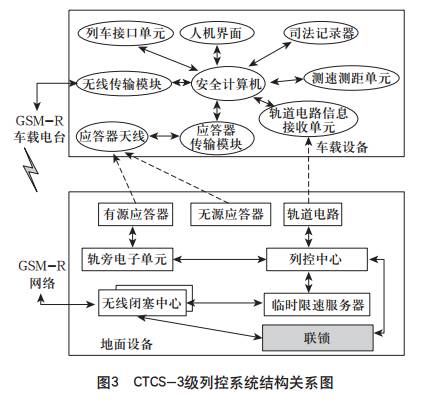
Currently, China’s CTCS Level 3 train operation control system is mainly divided into ground subsystems and onboard subsystems. The specific structure is shown in Figure 3.
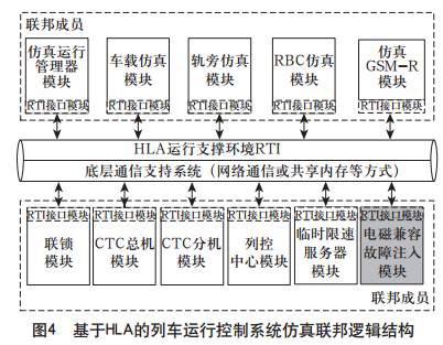
According to HLA design specifications, the entire train control system is regarded as a federation, with each sub-module joining the simulation federation as federate members. Additionally, to facilitate simulation management and fault collection analysis, a simulation manager federate member is included. The HLA/RTI environment-based train control system simulation federation is illustrated in Figure 4.
Each module of the HLA-based train operation control simulation system has a corresponding fault-safety mechanism design. Based on the existing platform, detailed research and analysis are conducted on the modules planned for testing, providing an EMC fault case library that aligns with actual conditions, and coding the EMC fault cases according to a pre-designed data format. Combining the characteristics of EMC fault scenarios in the train control system, EMC faults are injected into critical devices, and the response results of related subsystems affected by the fault are analyzed to verify whether they can correctly meet functional logic.
3 Design of EMC Fault Injection Case and Simulation Testing
3.1 Markov Chain-Based EMC Fault Analysis
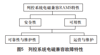
The EMC issues of the train control system mainly arise from: EMC fault sources caused by interactions between sub-devices during the system design phase, fault sources introduced by other devices during the system operation phase, and fault sources introduced by changes in device operating states during the system maintenance phase. The RAMS analysis relationship of the EMC characteristics of the train control system is shown in Figure 5.
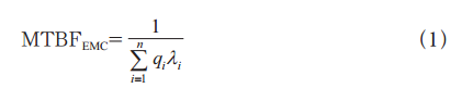
The reliability of the train control system is mainly measured by the Mean Time Between Failures (MTBF), which indicates the average time between electromagnetic compatibility faults of the subsystems or sub-devices of the train control system, represented by the formula (1):
The maintainability of the train control system is mainly represented by the Mean Time To Repair (MTTR), which indicates the time taken for the system to recover from an electromagnetic compatibility fault after it has been identified, represented by formula (2):
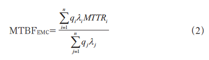
Where: qi is the number of device i; λi is the failure rate of device i.
The availability of the train control system is usually characterized by the ratio of the time the system is available without electromagnetic compatibility faults to the total operating time of the entire system. The safety level of the train control system indicates the level of acceptable electromagnetic compatibility risks.
In the analysis of electromagnetic compatibility faults in the train control system, the Markov method can achieve quantitative analysis of EMC faults, fully reflecting the impact of testing and maintenance on the system and reflecting the time-varying characteristics that the system may possess in real-time. Using the Markov-based analysis method can calculate different RAMS indicators.
In the Markov chain analysis model, let {X=(n),n=0,1,2,…} be a random process taking values in E={0,1,2,…} or E={0,1,2,…N}, where the former indicates an infinite number of states and the latter indicates a finite state space. Let the discrete state space of the train control system’s EMC characteristics be E. For any m non-negative integers n1, n2, …, nm (0≤n1≤n2≤…≤nm) and any natural number k, as well as any i1,i2,…,im,j∈E, the following condition is satisfied:
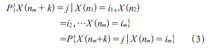
In formula (3), if nm is the current time, n1, n2, …, nm-1 are past times, and nm+k is the future time. The process of EMC fault analysis based on the Markov chain is shown in Figure 6.

To establish a complete Markov model, the following steps can be taken:
1) Establish the model by analyzing the system’s functionality and structure to determine the system is in EMC fault state 1;
2) For fault state 1, determine the list of failure rate types caused by EMC faults for all components in the system using the FMEA method;
3) For different types of failure rates caused by EMC faults, analyze the new states caused by transitions;
4) For existing failure states caused by EMC faults, analyze the fault types and corresponding safety measures for different situations.
5) For the system’s degraded working state, continue to create a list of all failure rates caused by EMC faults for all normal components; and execute steps 3 and 4 based on the list;
6) Continuously create the Markov model until all components in the system produce failures caused by EMC faults.
3.2 Construction of EMC Fault Case Database
The EMC fault case database is as follows.
Researching the functionality and safety of the train operation control system, analyzing and summarizing all possible types of EMC faults in all sub-devices within the system, and establishing the corresponding EMC fault case database. Based on the functional characteristics of the train operation control system, combining fault cases to generate corresponding sequences of EMC faults. All fault cases and fault sequences will serve as the data source for testing the fault injection software.
1) Format of EMC Fault Cases
Case Number: Fault Type → Fault Device → Fault Location → Fault Description → Expected Response Device of Target System → Expected Behavioral Response of Target System.
2) Example of EMC Fault Cases
a. Conductive interference caused by traction current return: interference voltage caused by unbalanced traction current → damage or failure of track circuit components (fuse blown, cable, choke transformer burnt, etc.) → locking route status as “in use” → interlocking sub-device sends route locking information to RBC → RBC recalculates MA based on train occupancy information and route information → RBC confirms safety hazards and sends emergency stop information to the train → onboard equipment generates a shortened new MA and sends confirmation of executing conditional emergency stop information to RBC, and the train brakes according to the shortened MA.
b. Inductive and capacitive coupling interference of signal cables: magnetic field generated by contact network current induces longitudinal electromotive force in signal cables → damage or failure of track circuit components (fuse blown, cable, choke transformer burnt, etc.), switch loses indication, interlocking cannot process the route → the train cannot update MA and operates in visual driving mode (OS) → after entering the fully monitored section and obtaining new driving permission, the train automatically switches to fully monitored mode (FS).
c. Inductive interference of track circuits by operating electric locomotives: high harmonic voltage in the power grid induced in the track circuit → track relay incorrectly activated → track circuit logic displays corresponding operational section as idle (actually occupied by the train) → the train operates according to the original MA; harmonic current → track relay incorrectly deactivated → track circuit indicates occupied (actually not occupied by the train) → the train will implement emergency braking.
d. Electromagnetic induction and radiation interference to signal systems: sudden electromagnetic fields generated by the contact network through coupling or radiation → induced electromotive force in information transmission channels → GSM-R unit failure → interruption of communication between RBC and the train → the train cannot update MA → the train implements maximum common braking.
e. Interference of locomotive signal devices by the locomotive: electromagnetic interference signals generated by traction motors or power fluctuations → aerial radiation or inductive coupling → overspeed protection device failure → the train will implement emergency braking.
3.3 Simulation Testing and Result Analysis
1) Set Testing Fault Cases
Run the HLA-based train control system simulation platform, open the fault injection federate member, select the corresponding fault case from the case database for the tested function, and inject it into the train control system simulation platform.
2) Fault Case Decomposition
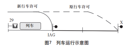
Taking the track circuit failure caused by inductive interference from operating electric locomotives as an example, the train control simulation system should detect the fault and respond as follows: high harmonic voltage in the power grid induces in the track circuit, damaging or causing faults in track circuit components, leading to incorrect track relay activation. As shown in Figure 7, the track circuit shows occupied (actually not occupied by the train), resulting in the original MA becoming invalid and urgently needing to be updated to ensure safe train operation.
3) Experimental Analysis
As shown in Figures 8 (a) and 9, at this time, the track circuit occupancy shows normal, and the EOA of the MA calculated by RBC is the downlink entrance signal X, as shown in Figure 10 (a).
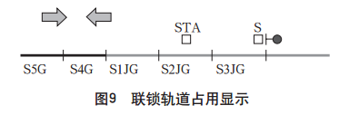

After injecting the relay fault through the fault injection module, the track circuit shows occupied (actually not occupied by the train), as shown in Figure 8 (b). The TCC sends the track occupancy information to the RBC, which recalculates the MA based on train occupancy information and route information, as shown in Figure 10 (b). The RBC confirms the presence of safety hazards and sends emergency stop information to the train. The onboard equipment generates a shortened new MA and sends confirmation of executing conditional emergency stop information to the RBC, and the train brakes according to the shortened MA.
The system response time in the test is defined as the time consumed from the fault injection module sending the fault command to the TCC module recognizing the track occupancy. The fault recovery time is defined as the time from the moment TCC recognizes the track occupancy to the moment the train receives the updated MA and implements emergency braking until it stops.
Five tests were conducted for this fault case, with the test records shown in Table 2.
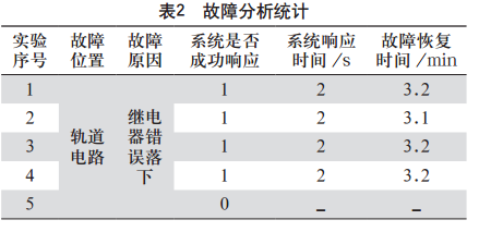
In the fifth experiment, the main reason for the system’s unsuccessful response was due to information loss or errors during the UDP communication process in the simulation, leading to the TCC module not correctly receiving the fault command.
The test results indicate that the fault injection simulation method proposed in this paper can effectively test and verify the electromagnetic compatibility characteristics of the simulation system. Extensive experimental testing of the probability of EMC faults indicates that this EMC fault case can cause damage to track circuit equipment but does not lead to further serious consequences for the train. The simulation system has already set up a handling mechanism for this EMC fault case, and its functionality is intact, effectively demonstrating the fault handling mechanism and corresponding functional design of the train control system.
4 Conclusion
The fault injection method is an effective means of system analysis and testing verification based on simulation testing. This paper applies the simulation fault injection method to the electromagnetic compatibility of train operation control systems. Based on the HLA train operation control system simulation platform, a Markov chain-based electromagnetic compatibility fault analysis method is proposed, along with the establishment of an EMC fault case database. Combining typical electromagnetic compatibility faults in the train control system, corresponding fault testing cases are established, tested on the train control simulation platform, and safety analysis results and fault statistical characteristics of the train control system are obtained. The experimental results show that the fault injection method can effectively assess and analyze the EMC fault characteristics of the train control system.
The subjects of the simulation tests in this paper are virtual train control devices, whose simulation logic and communication protocols between devices are basically consistent with the logic of the CTCS Level 3 control system. The test results of the virtual devices can reflect the causes of faults and their resulting consequences, and can be applicable to actual devices to some extent. However, since actual devices involve more complex hardware operating conditions and environmental situations during operation, to more effectively represent the real working conditions of actual devices, the next step of this paper will study the semi-physical simulation of the train control system and its fault analysis methods.
References
[1] Shi Junyou, Li Zheng, Luo Mingzhu, et al. Design and Implementation of Fault Injection Control Software[J]. Measurement and Control Technology, 2008, 27(4): 65-67.
[2] Wang Shengwen. Research on Software-Based Fault Injection Methods[D]. Harbin: Harbin Institute of Technology, 2005.
[3] Arlat J, Aguera M, Amat L, et al. Fault Injection for Dependability Validation: A Methodology and Some Applications[J]. IEEE Transactions on Software Engineering, 1990, 16(2): 166-182.
[4] Mealing SW, Hinsley W. System Assurance by In-Service Reliability Evaluation[C]. The Institution of Engineering and Technology International Conference on System Safety. IET, 2006: 130-135.
[5] Feng Xuan. Research on Software Fault Injection Methods[J]. Computer Optical Disk Software and Applications, 2010(16): 67-67.
[6] Wan Lin, Fan Ming. Research on Train Operation Control System Simulation Platform[J]. Railway Communication Signal, 2010, 46(8): 71-74.
[7] Maxion RA, Olszewski RT. Detection and Discrimination of Injected Network Faults[C]//International Symposium on Fault-Tolerant Computing, June 22-24, 1993, c1993: 198-207.
[8] Stott DT, Ries G, Hsueh MC, et al. Dependability Analysis of a High-Speed Network Using Software-Implemented Fault Injection and Simulated Fault Injection[J]. IEEE Transactions on Computers, 1998, 47(1): 108-119.
[9] Hu Baoqing. Fundamentals of Fuzzy Theory[M]. Wuhan: Wuhan University Press, 2010.
[10] Liu Puyin. Fuzzy Theory and Its Applications[M]. Beijing: National Defense University Press, 1998.
[11] Liu Yiyong. Research on Optimization Configuration Strategies for Electromagnetic Compatibility Measurement Systems[D]. Xi’an: Northwestern Polytechnical University, 2006.
[12] Cheng Weilan, Huang Jian. Discussion on the Structure of Electromagnetic Compatibility Database for Ships[C]. National Academic Conference on Electromagnetic Compatibility, 1999.
[13] Zhang Wencang, Su Donglin. Application of Database in Automatic Testing System for Electromagnetic Compatibility[C]. National Academic Conference on Electromagnetic Compatibility, 2005.
[14] Liu Pengcheng. Principles and Techniques of Electromagnetic Compatibility[M]. Beijing: Higher Education Press, 1993.
[15] Wang Feng, Li Junhua. Research on Electromagnetic Compatibility of Ships Based on Simulation and Database Structure Design[C]. China Shipbuilding Engineering Society 2005 CAD/CAM Academic Exchange Conference, 2005.
(Received Date: 2017-02-13)
Original article from the official platform of Railway Communication Signal Engineering Technology Journal