
Laser fault injection in 32-bit microcontrollers: from flash interface to execution pipeline

Written by | Yang Xue
Edited by | Liu Mengdi
Background
With the development of the Internet of Things, the demand for microcontrollers (MCUs) has increased significantly, and the data they process is often critical and valuable. In addition to network attacks, many physical techniques have emerged to extract unauthorized data because these devices are physically accessible.
Among the relevant techniques, Fault Injection (FI) is a proactive side-channel attack method that induces computational faults in the target processor by altering the chip’s physical operating environment (e.g., overvoltage, undervoltage, overclocking, exposure to high or low temperatures, or laser), such as skipping instructions, thereby changing the device’s operation. This results in a fault outcome that can further utilize Differential Fault Analysis (fault vs. no fault) to extract unauthorized data.
Based on this information, Vanthanh Khuat, Jean-Luc Danger, Jean-Max Dutertre, and others from École Polytechnique have discussed a laser fault injection method targeting 32-bit microcontrollers at FDTC 2021, achieving fault identification and description from the flash interface to the execution pipeline by collecting faults from all locations and analyzing their behavior.[1]
Previous Work
Related studies have demonstrated that laser fault injection can cause faults in volatile memory (static random-access memory (SRAM) or registers) while moving data from one component to another using different underlying techniques without affecting data stored in non-volatile memory.
Specifically, laser fault injection can be used to target and modify instructions, resulting in instruction corruption, skipping, etc. In 2019, Dutertre et al. reported a robust laser fault injection-induced multi-instruction skip fault model, in which the authors were able to skip an arbitrary number of instructions, up to 300 instructions, using laser pulses with relatively long pulse widths.[2]
Experimental Content
The authors conducted experiments using the SAMD21G18A with an ARM Cortex-M0+ core (two-stage pipeline). The laser fault injection setup is shown in Figure 1, where the laser platform consists of a laser source, microscope, XYZ working stage, infrared (IR) camera, and computer. The laser source can produce laser pulses with a wavelength of 1064 nm, allowing light to pass through several hundred µm of silicon. The pulse width of the laser can be tuned in the range of 50 ns to 1 s. Additionally, the laser source allows for programmable delay with a power range of 0 to 3 watts. The light is directed to the microscope and focused through it.
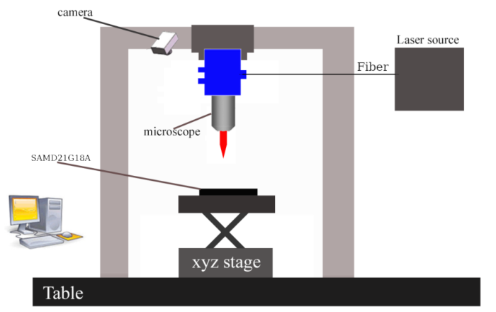
Figure 1 Laser Injection Workbench
Using the infrared camera to observe the location of the laser spot in the device, the authors performed laser fault injection under twelve conditions, at six points (as shown in Figure 2), with and without cache enabled.
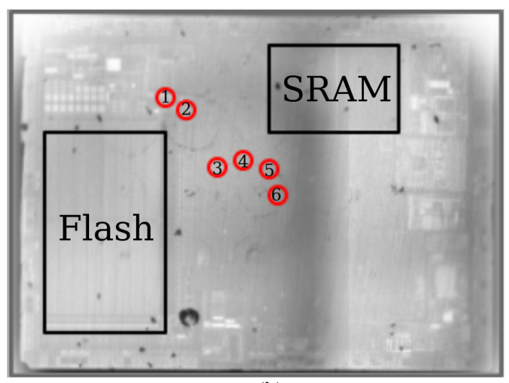
Figure 2 Corresponding Points Captured by Infrared Camera
Experimental Results
-
Replay and Skip Fault Phenomena
First, the fault phenomena are described, with skip faults defined as shown in Figure 3 (left) and replay faults defined as shown in Figure 3 (right).
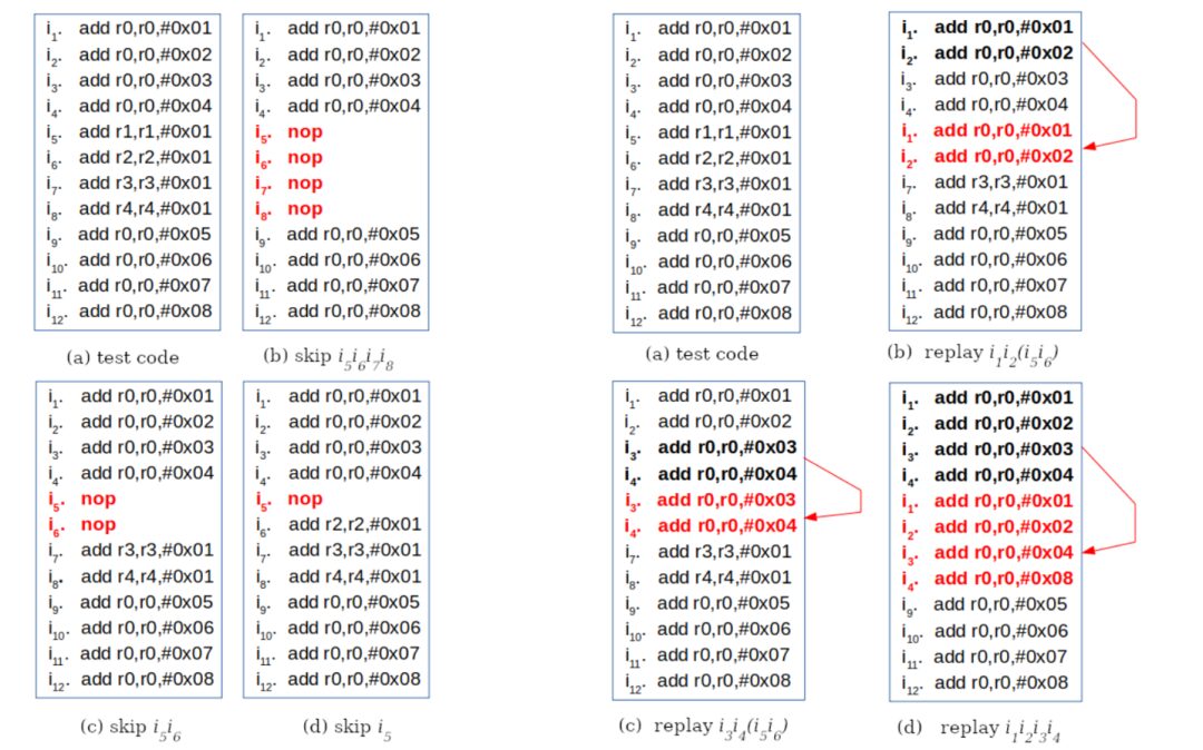
Figure 3 Skip Fault Definition (left), Replay Fault Definition (right)
Laser fault injections were performed at six points, observing different fault phenomena. Some of the fault phenomena are shown in Figure 4, categorized into replay and skip fault phenomena. When the cache is disabled, the buffer size is 32 bits, corresponding to 2×16-bit instructions, resulting in fault phenomena of skipping or replaying two instructions; when the cache is enabled, the buffer size is 64 bits, corresponding to 4×16-bit instructions, resulting in fault phenomena of skipping or replaying four instructions.
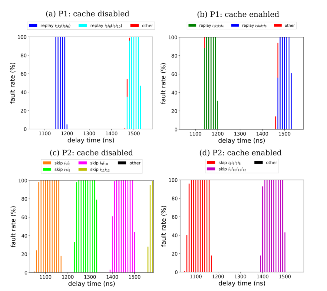
Figure 4 Fault Phenomena Observed at Points P1 and P2
Analysis reveals that replay faults are caused by the laser preventing updates to the flash interface buffer; skip faults are caused by one or more bits in the buffer content being damaged by the laser.
-
Fault Occurrence Mechanism
Based on the number of fault instructions and the reported fault behaviors with cache disabled and enabled, an attempt was made to determine at which stage the instruction fails. To detect and roughly classify induced faults, it is first necessary to understand the instruction flow from flash memory to the core pipeline. Figure 5 shows the block diagram of the non-volatile memory (NVM) of the SAMD21G18A. Instructions typically stored in NVM (such as flash memory) are loaded into the flash interface and its buffer before being transferred to the AHB bus. The 32-bit data corresponding to 2×16-bit instructions is loaded into the AHB bus every two clock cycles. The instructions are then loaded into the pipeline from the AHB bus.
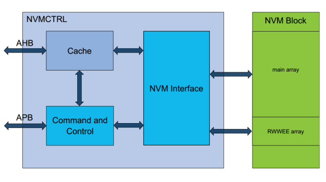
Figure 5 SAMD21 NVM Interface
Experiments have shown that faults may occur in the flash interface buffer when using EMFI (Electromagnetic Fault Injection) and LFI (Laser).
The fault occurrence mechanism is illustrated in Figure 6. Assuming that the AHB bus has already been requested, it is time to place HTRANS and HADDR onto the bus. HRDATA is one cycle slower than HADDR. Therefore, in Figure 6 (b), due to a fault in the longitudinal data update of AHB, instructions i5 and i6 are replayed; in Figure 6 (c), due to a bit fault in HRDATA, instructions cannot be correctly identified, leading to instructions i7 and i8 being skipped; in Figure 6 (d), due to the core pipeline’s fetch stage receiving bit-damaged instructions, instruction i6 is skipped; in Figure 6 (e), due to the execution stage of the core pipeline receiving bit-damaged instructions, instruction i5 is skipped.
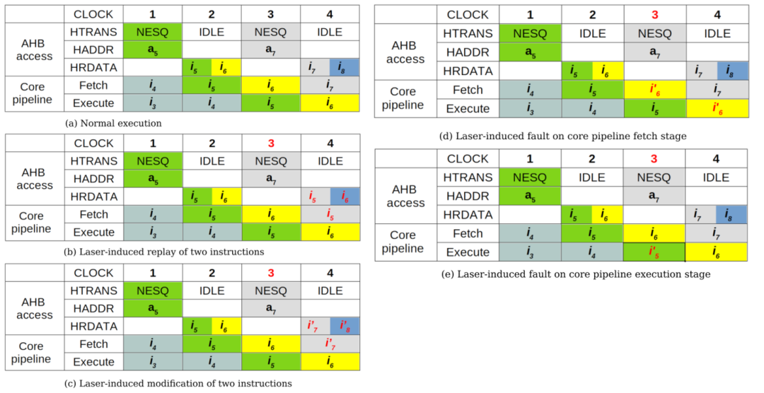
Figure 6 Fault Occurrence Mechanism
In summary, different laser fault injection points will affect different processes of instruction pipeline processing, which is consistent with the different fault occurrence times observed by the authors.
Relevant scholars have also discussed the impact of PW and power on the success rate of fault injection. The larger the laser pulse width, the more instructions are faulted; the higher the laser power, the higher the probability of faults occurring.
Conclusion
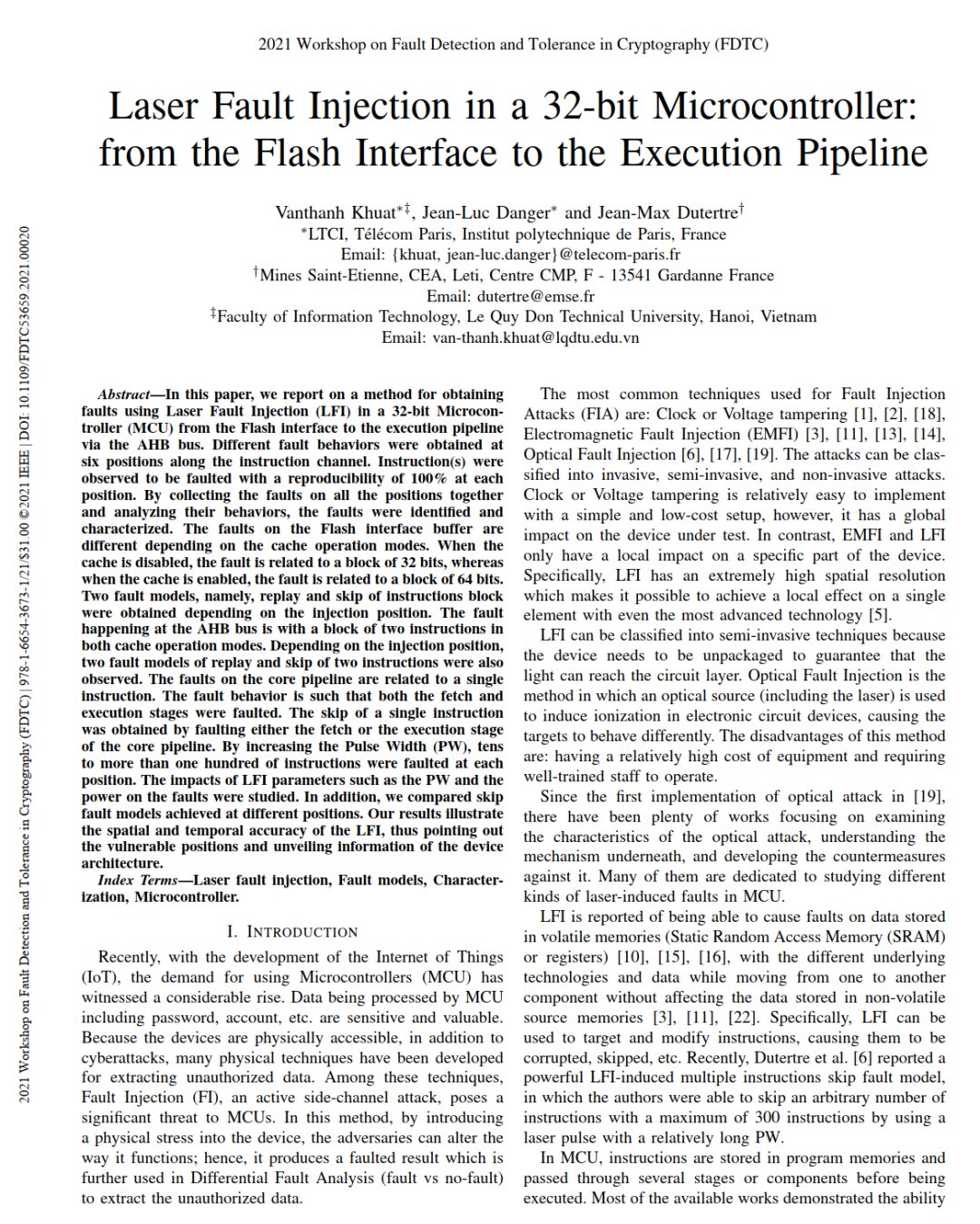
This paper introduces a method for obtaining faults in a 32-bit microcontroller (MCU) through laser fault injection (LFI) from the flash interface to the execution pipeline via the AHB bus. Different fault behaviors were obtained at six positions in the instruction channel; by collecting faults from all positions and analyzing their behaviors, it is possible to identify and describe faults and determine that the faults on the flash interface buffer vary based on cache operation modes; two fault models of replay and skip were obtained based on different injection positions, and the effects of laser fault injection parameters such as pulse width and power on faults were studied.
The results of this paper illustrate the spatial and temporal accuracy of laser fault injection, indicating vulnerable locations and revealing information about device architecture.
References
[1] V. Khuat, J. -L. Danger and J. -M. Dutertre, “Laser Fault Injection in a 32-bit Microcontroller: from the Flash Interface to the Execution Pipeline,” 2021 Workshop on Fault Detection and Tolerance in Cryptography (FDTC), 2021, pp. 74-85, doi: 10.1109/FDTC53659.2021.00020.
[2] Jean-Max Dutertre, Timothé Riom, Olivier Potin, and JeanBaptiste Rigaud. Experimental analysis of the laser-induced instruction skip fault model. In Nordic Conference on Secure IT Systems, pages 221–237.Springer, 2019.