

 For more information about meetings and live classes, please inquire via WeChat “NewCarRen”.

Abstract
In recent years, the integration of advanced technologies in electric vehicles (EVs) has been increasing, making it crucial to assess the risks associated with the deployed technologies. Functional safety is necessary for automobiles to ensure human life safety. The Battery Management System (BMS) chip is one of the important components in electric vehicles, using the Serial Peripheral Interface (SPI) to communicate with external ICs to monitor the battery status used in electric vehicles. To obtain functional safety certification for the chip, each module on the chip should have a safety architecture around it and should undergo functional safety validation. This paper performs fault injection based on Failure Mode Effects and Diagnostic Analysis (FMEDA) to validate the SPI safety architecture recommended by ISO 26262. For single point failures in the SPI block, the diagnostic coverage reaches 97.2%, which is sufficient to achieve a single point fault metric (SPFM) of 99% for the entire chip.
1. Introduction
As advanced electronic technologies push the automotive industry to new heights, Original Equipment Manufacturers (OEMs) need certified semiconductors for safety. The automation of E/E systems in vehicles is evolving into a complex process, aiming to provide many advanced functions such as electric power steering, ADAS, braking systems, airbags, etc., all of which require safety assurances. As these cutting-edge technologies are integrated into vehicles, manufacturers now need to assess and examine the risks associated with the technologies they wish to use. Functional safety is necessary for automobiles to ensure human life safety. Functional safety (FuSa) refers to the ability of the entire system to continue to operate reliably as intended, even in the event of accidental occurrences. Furthermore, the system ensures that there are no unacceptable risks of personal injury or damage. The functionality of modern vehicles is made possible by the extensive use of electronic products. This has led to a demand for FuSa semiconductor chips in the automotive industry. For System-on-Chips (SoCs), especially as sub-micron designs are entered, sensitivity becomes greater. High levels of safety can make the product stand out and change consumer perceptions.
The BMS is one such SoC used in electric vehicles and must meet functional safety standards. The BMS can control the rechargeable battery environment, protect the battery from exceeding its safe operating parameters, monitor battery conditions, report derived auxiliary data, balance, and verify the battery’s electronic systems. Considering scenarios where some BMS chips do not have the capability to measure current, external ICs that measure current attempt to send current data that needs to be fed to the BMS chip, or monitor battery voltage. To send and/or receive information to each other, these ICs must be able to communicate with each other. Therefore, the communication protocol is crucial for a BMS with multiple ICs to communicate with each other. SPI is a protocol that provides an easy-to-implement and low-cost interface between microcontrollers and their peripherals. The SPI protocol uses a serial clock generated by the master device to synchronize the transmission and reception between the master device and the slave device. One device is regarded as the master device of the bus (in this case, the BMS is the master device), while all other devices (peripheral ICs and even other microcontrollers) are regarded as slave devices.
ISO 26262 requires the calculation of the hazard rate caused by random hardware failures. During the product development phase, hardware and software development essentially attempts to analyze the BMS at the system level first, then at the component level, deriving safety requirements from the functional safety concept, developing the system architecture, and defining safety mechanisms for failure detection and avoidance. FMEDA can identify potential failure modes and the impacts of these failures at multiple system levels, which is often the first step in understanding system safety. Failure is the starting point for analysis, which may later lead to errors and failures. To ensure ISO 26262 safety requirements, safety mechanisms are designed for each function in the BMS. SPI is a peripheral in the BMS, and a safety architecture is designed around it, with safety mechanisms for every failure mode in the functionality. Any safety architecture designed to meet the highest safety standards for various purposes in the automotive industry should be verified using fault injection. By introducing faults into the design and monitoring its response to the faults, fault injection techniques can be used to evaluate the reliability of the design under test. Digital fault injection runs on RTL/GLS (netlist), injecting faults at the input/output ports and internal nodes of each block during top-level verification. Then it checks whether the injected faults can be detected by the safety mechanisms. Diagnostic coverage (DC) is a benchmark for safety measures that detect hazardous failures, and this paper will calculate it for the SPI safety architecture.
2. Functional Safety Standards
The International Electrotechnical Commission (IEC) 61508 is a single standard addressing functional safety for all products and industries. The IEC has published a global standard that outlines the use, design, deployment, and maintenance of safety-related technologies. The functional safety of electrical, electronic, and programmable electronic safety-related systems (E/E/PE or E/E/PES) is the title of this document. IEC 61508 is the fundamental functional safety standard applicable to all fields. Although this standard applies to all industries, each industry has its nuances, which is why many industries have created their own standards based on IEC 61508. The design verified in this paper belongs to the BMS of the automotive industry.
A. ISO 26262
ISO 26262 is a global standard focused on safety-critical systems in the automotive industry, primarily derived from IEC 61508. It is used for E/E systems in vehicles, including hardware and software components. It outlines the safety-related functions of the system and the requirements that the processes, techniques, and tools used during development must meet. As the automotive industry becomes increasingly complex, more effort must be made to provide systems that meet safety requirements. The goal of ISO 26262 is to provide a single safety standard for all E/E systems in vehicles. The functional safety of products is systematically managed by ISO 26262 at the system, hardware, and software levels during the development process. It has an automotive safety lifecycle that outlines each stage of production, from management to development to production to operation to service to decommissioning. Automotive Safety Integrity Level (ASIL) is used to establish applicable standards for ISO 26262 to reduce unacceptable residual risks and further serves as a unique risk-based approach to identify risk categories in the automotive industry. The specifications for defining architecture, design development, verification, integration, and confirmation processes to ensure acceptable safety levels.
B. Automotive Safety Integrity Levels
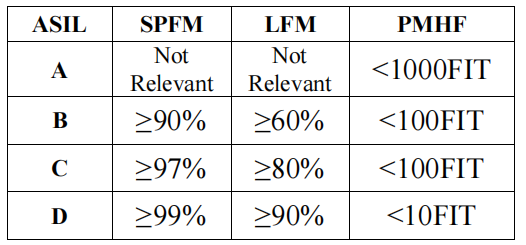
ASIL is a crucial component of ISO 26262 compliance. The design and development of systems must comply with ASIL, which is determined at the beginning of the chip development phase. The planned functions of the system are checked against any potential hazards. The estimation of the risk is based on the probability of exposure, the driver’s possible controllability, and the severity of the possible outcomes when critical events occur, leading to the derivation of ASIL. Regardless of the technology used in the system, ASIL entirely depends on the potential harm to the driver and other road users. Any safety requirements are assigned an ASIL level of A, B, C, or D. Systems marked with “D” are considered the most safety-critical and are subject to the strictest testing standards, while processes marked with “A” are considered the least safe. The minimum testing standards outlined in the ISO 26262 standard simplify the selection of testing methods. Based on ASIL levels, the single point fault metric (SPFM), latent fault metric (LFM), and hardware failure probability metric (PMHF) should be calculated and further satisfied, as shown in Table 1.

SPFM measures the safety of the system against single point faults (SPF) and residual faults (RF); the higher the SPFM, the better the safety. For example, if the SPI receives corrupted data and it’s not detected, it will always lead to incorrect output, which will definitely result in severe situations. For ASIL D, 99% SPFM should be achieved; simply put, more than 99% of single point faults should be detected. SPFM can be calculated as the weighted average of the diagnostic coverage calculated for each block on the chip concerning the SPF considered. The weights are proportional to the area occupied by the blocks on the chip. The latent fault metric measures the safety of the system against multiple point faults (MPF); the higher the LFM, the better the safety. For ASIL D, more than 90% of MPFs should be detected and mitigated. The probability metric of random hardware failure is the average probability of system failure occurring per hour over the entire operational lifetime of the system. For ASIL D, ≤10 FIT should be achieved. Here, the real-time failure (FIT) rate is determined by the expected number of random failures occurring within one billion (109) device operating hours.
This paper focuses on executing functional safety verification of SPI by assessing the safety of SoC-level design to meet the FuSa standard compliant with ISO 26262:2018, targeting the top-level goal of ASIL D. Here, to reach this level, a diagnostic coverage greater than 97% for SPF should be achieved, which is determined based on the weighted average formula used for calculating SPFM, based on which industry-standard tools are available to calculate LFM and PMHF. To define the verification program, several provisions of ISO 26262:2018 were adopted:
1. ISO 26262-5:2018 Section 7.4.3 – Safety analysis of hardware design should be conducted through deductive and inductive analysis to determine the causes of failures and their effects.
2. ISO 26262-5:2018 Section 7.4.4 – Hardware design should be verified using hardware design verification methods (e.g., hardware design walkthroughs, checks, and simulations) to meet safety-related special characteristics to achieve functional safety during production and service.
3. ISO 26262-5:2018 Section 7.4.5 – If safety analysis shows these characteristics are relevant, safety-related special characteristics should be specified.
4. ISO 26262-5:20182-11:2018 Section 4.8.1 – Fault injection at the semiconductor component level is a known method that can be used to support multiple activities in the lifecycle when the safety concept involves semiconductor components.
5. ISO 26262-11:2018 Section 4.8.2 – Fault injection characteristics or variables that assist in verifying the plan.
6. ISO 26262-11:2018 Section 4.8.3 – The results of fault injection can be used to verify the safety concepts and fundamental assumptions listed in ISO 26262-11-2018 Section 4.8.1 (e.g., effectiveness of safety mechanisms, diagnostic coverage, and number of safety failures).
7. ISO 26262-11:2018 Section 5.1.10 – Verification using fault injection simulation can be applied to both permanent and transient faults. Utilizing fault injection in design models can successfully assist in verifying safety faults and calculating their numbers and failure mode coverage. Injecting faults and using explicitly specified observation points to determine whether the faults cause measurable impacts is also possible. Additionally, it can assist in calculating and verifying the values of failure mode coverage. Injecting faults that can cause measurable impacts and determining if these faults are detected or controlled by safety mechanisms within the maximum fault handling time interval.
C. Fault Injection Terminology:
Fault injection is an indispensable step and valuable technique for functional safety verification. This paper is an automotive application, particularly focusing on a simulation-based fault injection platform. Simulation-based fault injection is an automatic fault injection simulation used to simulate “field faults” to validate safety architecture. Through Verilog systems, random fault injection simulation platforms can implement fault models such as: stuck-at-0, stuck-at-1, and bit-flip, randomly inserting them into the design to analyze fault coverage. By performing fault injection, erroneous output signals are generated, which are errors that will further lead to failures. The simulation environment for simulation-based fault injection consists of a fault injector, fault library, controller, and data analyzer.
In simulation-based fault injection, faults can be modeled as permanent faults and transient faults. Permanent faults are a type of persistent failure, such as a short circuit between wires, pins, or tracks, which persists until the faulty component is repaired or replaced. Examples of permanent faults in the real world include disk head crashes, software bugs, and burned-out power supplies. Permanent faults continue to exist in the system until the error is fixed. Further in simulation-based fault injection, permanent faults can be modeled in two different ways:
1. Stuck-at-0 or SA0: The signal value is forced to 0 from the start of fault injection until the end of simulation.
2. Stuck-at-1 or SA1: The signal value is forced to 1 from the start of fault injection until the end of simulation.
Transient faults refer to faults that recover after a short power outage or faults that appear for a short time and then cease to exist. In simulation-based fault injection, transient faults can be modeled in two different ways:
1. Single Event Upset or SEU: This model flips the output value of sequential elements and retains the modified value, assigning a new value to it. This fault model can be applied to the outputs of timing elements such as memory, flip-flops, and latches.
2. Single Event Transient or SET: This model flips the value of a signal and retains the modified value for a specified period. This fault model can be applied to any type of signal, such as networks or registers.
In fault injection activities, multiple fault injection runs are executed to generate safety metrics. Each fault injection simulation run executes normal simulation and fault simulation. Normal simulation must run to generate reference values for fault injection, while fault simulation is the subsequent simulation that classifies any faults injected into the design. In this process, reference values of observation points are captured during normal simulation runs (defined before good simulation). These observation points help better classify injected faults at one or more networks/nodes.
1. Functional Gate Pulse: All main outputs in the design considered will be used to detect whether injected faults at nodes/ports lead to functional failures.
2. Checker Gate: These outputs will be used to detect whether safety mechanisms detect faults injected at nodes/ports. All outputs of safety mechanisms are checker flashes.
Functional gates and checker gates are needed to classify injected faults. Faults propagating to functional gate flashes are hazardous and will be detected if they propagate to checker gate flashes. Injected faults can be classified into the following categories:
1. Dangerous and Detected (DD): Any injected fault that propagates to both functional gate flashes and checker gate flashes is considered DD. If a fault is classified as DD, the safety architecture can detect a hazardous fault.
2. Dangerous and Undetected (DU): Any injected fault that propagates only to functional gate pulses but not to checker gate pulses is considered DU. If a fault is classified as DU, the safety architecture cannot detect a hazardous fault.
3. Undetected and Detected (UD): Any injected fault that propagates only to checker gate pulses but not to functional gate pulses is considered UD. If a fault is classified as UD, the safety architecture is more cautious.
4. Undetected and Undetected (UU): Any injected fault that does not propagate to any functional gate pulses and checker gate pulses is considered UU. If a fault is classified as UU, it is due to a lack of excitation, which may ultimately become DD/DU/UD when proper excitation is provided.
Diagnostic coverage is a benchmark for safety measures that detect hazardous failures. It can be expressed as:
3. Safety Architecture and Its FSV
A. SPI Safety Architecture
Single master communication protocol is called SPI. This means that only one device initiates communication with other slave devices. It is a high-speed synchronous serial IO port that shifts the length of serial bit streams (data) and transmits or receives them at a programmed bit transmission rate. When the SPI master device wants to send data to the slave device, the serial clock is activated at a clock frequency that both the master and slave devices can control. The slave device is selected by pulling down the corresponding slave select line. SPI can support duplex communication between the master device and its peripherals, as the master device generates data on the MOSI line while sampling the MISO line. It is important to remember that for communication to work correctly, the master and slave devices must use the same set of parameters, such as SCLK frequency, CPOL, and CPHA. Status, control, and data registers, shifter logic, baud rate generators, master/slave control logic, and port control logic make up most of the SPI design. The design of SPI is very similar to that detailed in the SPI module guide from Motorola Inc.
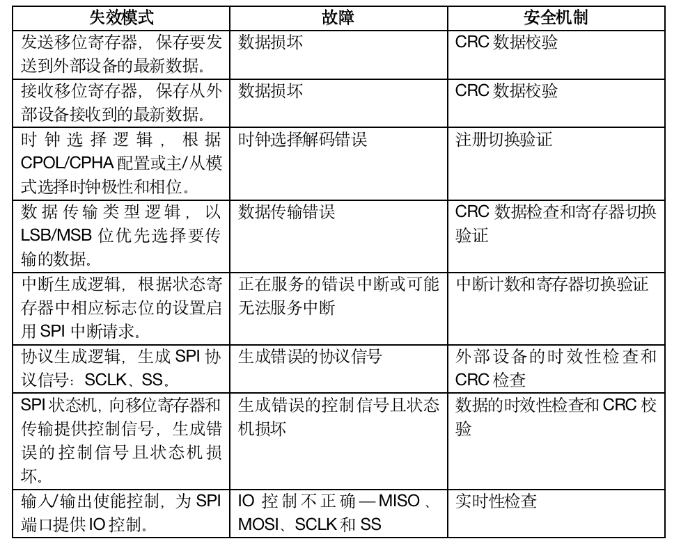
In the safety concept, functional safety requirements for the SPI design will be defined at the system level. The functional safety requirements for SPI provide data loss protection through the SPI path (sending and receiving), which requires functional safety and prevents faults. Data streams can flow from external ICs to the BMS SPI or flow from the BMS internal storage to external ICs through the BMS SPI. Any faults in the SPI path that may lead to functional failure and violate functional safety requirements are mentioned in the FMEDA. Any faults in SPI, its configuration/mode selection, and I/O pins may lead to data integrity, authenticity, and timeliness issues (e.g., initiation and completion of data transmission) and configuration errors. Furthermore, any faults in interrupt generation, identification, and servicing may manifest as unrecognized events and modify signal flows, leading to failures in data acquisition, transmission, and processing. Therefore, safety mechanisms should be designed to protect the defined functional safety requirements.
B. SPI FMEDA
First, FMEDA is executed by posing the question, “What do we want to avoid?” and “How can it happen?” and also adding a “diagnostic” section by asking, “What potential problems can arise?” FMEDA includes diagnostic coverage analysis to identify failure modes that could violate safety goals in the absence of safety mechanisms, and then identifies safety mechanisms that prevent these failure modes from violating safety goals. Once the netlist is available, block-level FMEDA is completed, aiding in implementing these mechanisms to detect all underlying failure modes. The goal is to calculate the coverage of failure modes that violate safety goals. Functional analysis forms the basis of FMEDA.
4. Execution
A. Safety Mechanisms
Safety mechanisms are on-chip functionalities that can detect and mitigate or make the design fault-tolerant, reporting these faults when detected. These mechanisms can be purely hardware, purely software, or a combination. The safety mechanisms proposed to protect SPI from the impact of failures are purely software safety mechanisms. After block-level FMEDA is executed, these mechanisms will be implemented to detect all underlying failure modes. These must be implemented in parallel when SPI operations occur. The proposed safety mechanisms are:
1. CRC Check for Data: CRC provides error codes. It detects faults that lead to mismatched expected data.
2. Interrupt Count and Timeliness Check: Detects any lost or spurious interrupts, leading to random failures in interrupt generation.
3. Register Switching Validation: Detects faults that lead to incorrect configuration and data transmission errors.
B. Simulation-Based Fault Injection
To support functional safety verification, the Cadence vManager safety client is used to automate fault injection activities using a defined process. By using input files, one can drive the safety client and the internal core engine running within the client, namely the Xcelium fault simulator. The input files are configuration files that define overall parameters, lists of faults that identify fault detection targets, lists of faults that identify fault diagnosis targets, a test list specifying one or more tests to run in a single session, and other script files necessary for running activities.
The vManager safety client supports various types of activity flows, using serial flows and concurrent flows. In serial: one fault is injected during the fault simulation run (i.e., the next fault can be injected after closing and reopening the run). The number of fault simulations equals the number of faults to be injected, which is a drawback of this process, and consumes more CPU memory due to the large number of simulations. In concurrent flow, multiple faults are injected for each fault simulation session each time it runs. The advantage of this process is that it is a throughput solution where multiple faults are injected and simulated together, and normal functionality and fault simulation are also simulated simultaneously. The tool retains a list of error values and good values for each node in the circuit. The drawback of this process is that overly active faults leading to a large number of simulation events do not propagate to their respective observation points. Such faults are marked as non-simulatable (NS) in the fault database of concurrent simulation. Additionally, if the erroneous simulation does not converge within the time calculated for good simulation values, the error will be reported as DU.
For the SPI module, all functional outputs are defined as functional gate pulses—MISO, MOSI, SCLK, SS, and corresponding input and output enables. All safety mechanism outputs are defined as checker gate pulses—CRC checks, timeliness checks, register switching configuration checks, and interrupt count and timing checks. All test cases are implemented for various SPI operation modes with safety mechanisms. The fault detection of SA0 and SA1 fault types at all unit ports in the SPI netlist is injected 80ns after the simulation starts, with a timeout factor of 10, meaning the fault simulation should execute up to 10 times the good simulation time.
5. Results and Discussion
A. Concurrent Runs
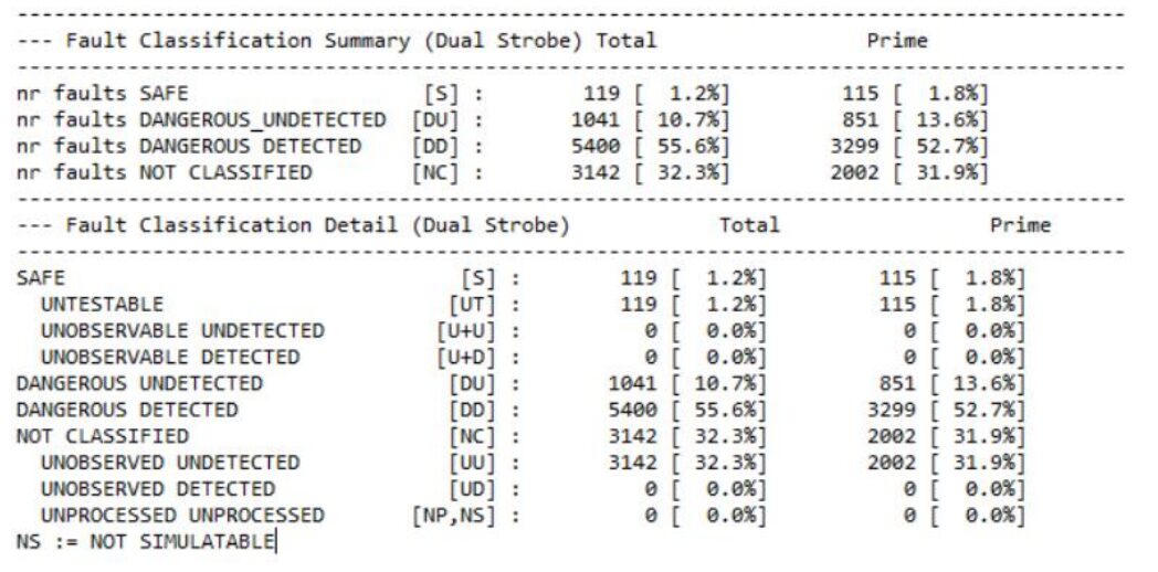
Concurrent simulation was completed with a group size of 2000, indicating that multiple faults injected and simulated are limited to each group of 2000. A total of 9702 faults were detectable in the design, with 119 reported as safe after structural analysis, and 9583 were testable, of which 6264 were primary faults. After completing the fault simulation, a session report was generated, achieving 83.84% DC.
B. Serial Runs
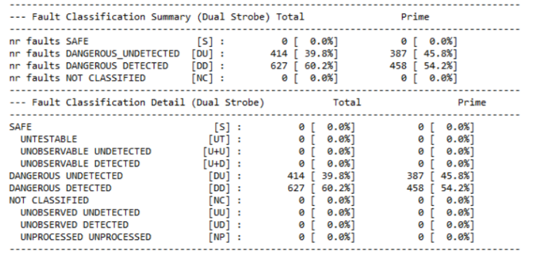
Although concurrent flow is a throughput solution, it has many drawbacks mentioned earlier in this paper. Therefore, the fault nodes reported as DU in the last run were extracted and used as input for the serial run in the fault list file. After completing the fault simulation, a session report was generated, and after merging the results of concurrent and serial runs, DC reached 93.57%.
C. DU Analysis
The achieved DC is insufficient and must be improved, which can be accomplished by reducing the number of faults reported as DU. To achieve this, a detailed DU analysis must be conducted on each reported node, which is only possible with a thorough understanding of the architectural design and finding a way to detect them or classify them as safe, even if they interfere with functional flashes but do not violate safety regulations. The vManager safety client also supports debugging modes, through which the waveforms can be rerun to compare the good simulation waveforms with the fault simulation waveforms and see when the injected faults affect different signals and logic blocks of the SPI.
To achieve the target ASIL D, by performing detailed DU analysis, moving them to the DD category by identifying detection mechanisms or moving them to the safe category by analyzing fault impacts, a diagnostic coverage of 97.2% for single point faults in the SPI block is achieved, making the entire chip sufficient to achieve 99% SPFM.
6. Conclusion
Based on FMEDA, safety mechanisms are implemented, and simulation-based digital fault injection is executed using the vManager safety client for safety mechanism (diagnostic) verification. Here, permanent faults at each unit port of the injected netlist define a set of functional and checker gate pulses, classifying faults as DD, DU, UD, UU, and safe. Using the tool-supported serial and concurrent flows, a diagnostic coverage of 93.5% is achieved for a total of 9702 instrumented faults, with 6047 reported as DD and 414 reported as DU. To achieve the target ASIL D, by performing detailed DU analysis, moving them to the DD category by identifying detection mechanisms or moving them to the safe category by analyzing fault impacts, a diagnostic coverage of 97.2% for single point faults in the SPI block is achieved, making the entire chip sufficient to achieve 99% SPFM.
7. Future Scope
Based on the challenges faced in completing functional safety verification more quickly, there are several ways to achieve the same results in a shorter time and provide recommendations for other designs.
1. Execute concurrent runs and then extract the fault list to run serial runs, which requires more time to create and execute setups. Therefore, a hybrid process can be created by requiring tool vendors to run concurrent and serial activities simultaneously through a single setup, extracting the fault lists for serial runs internally as faults are reported as NS and DU in concurrent runs. Then generate a merged data report, saving significant execution time.
2. For more complex designs with >40000 faults, injecting faults for all possible faults is not a good approach; a sampling method should be used where the tool randomly injects faults of specified values into the design. Then analyze the results of fewer faults and modify test cases to achieve the DC required for this set of faults. Performing 2 to 3 iterations usually results in the DC values converging.
3. To execute DU analysis more quickly, formal methods can be used to understand which injected faults can be detected or classified as safe.

🎁Free trial application for REANA cybersecurity analysis tool, scan the code to add Niu Xiaoke’s WeChat, reply “REANA”.

🎁Free trial application for software static and dynamic code testing tools, scan the code to add Niu Xiaoke’s WeChat, reply “Software Testing”.

Automotive Safety Premium Services

For more industry news, technical interpretations, and inquiries, please visit the official website of New Car: i-newcar.com
【Automotive Chips】 Mechanisms for Testing Automotive Chips Using Vehicle Control Networks
【Automotive Chips】 Automatic Generation Method for Failure Modes of SoC Chips
【Automotive Chips】 Formal Fault Propagation Analysis Method for Functional Safety Design of Automotive SoCs
【Automotive Chips】 Hardware and Firmware Co-design Verification Method for Automotive SoC Chips Based on Fault Injection
Method for Functional Safety Argumentation of Neural Networks Based on ISO 26262
Safety Strategies for Autonomous Driving Vehicles Based on ISO/PAS 21448
How to Reduce the Time for ASPICE Assessment
Using Model-Based Methods to Assess the Safety of Automotive Embedded Software
Argumentation Ideas for Processes and Products in Automotive Safety Files
Automotive Cybersecurity Verification and Confirmation Testing
Safe and Reliable UDS Refresh via CAN Bus
Automotive Software Quality Management Integrating ASPICE, ISO 26262, ISO 21448, and ISO 21434
Design and Implementation Process of Advanced Driver Assistance Systems Based on Open Source AUTOSAR
Encrypted Storage of Automotive Data
Integration of ISO 26262 and ISO 21448 Development Processes for Autonomous Systems
Meeting Automotive Functional Safety Requirements Using GPIO
Beginner’s Guide to FMEDA
Estimating the Basic Failure Rate of Semiconductors Using IEC62380 and SN29500