Today, we will learn about the Siemens PLC control of a frequency inverter to implement a three-speed control circuit. First, let’s take a look at the schematic diagram: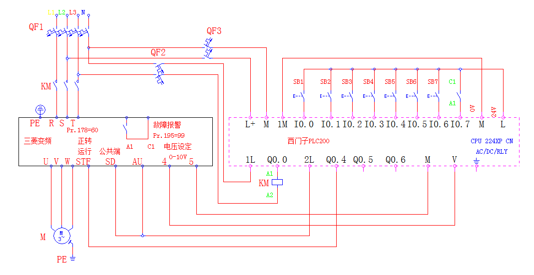 From the schematic diagram above, let’s analyze the components needed, and I have prepared an image for you:
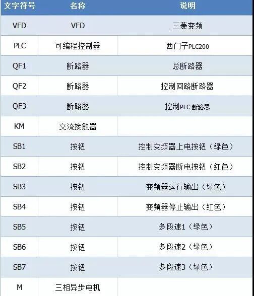 Parameter Settings:Pr.77: Parameter write prohibition selection: Parameter value is 1 (can be written during stop process).ALLC: Function: Clear all parameters: Set value is 1 (restore parameters to initial values).Pr.79: Function: Operation mode selection: Set value is 3 (external and panel PU combined operation).Pr.178: Function: Forward operation STF: Parameter value 60 (set terminal STF to forward operation command function).Pr.184: Function: Terminal 4 input selection AU: Parameter value: 4 (set AU terminal to valid/invalid selection for terminal 4 input, only valid when ON).Digital input common terminal SD: The common terminal for digital inputs SD, STF, STOP, etc.Analog common terminal 5: Frequency setting signal terminal 2, 14 common terminal, ON state input valid.Pr.267: Function: Terminal 4 frequency input mode selection: Parameter value: 2 (input 0-10V signal valid between terminals 4-5).Pr.195: Function: Multifunction terminal function selection: Parameter setting 99 (we use normally open point A1, C1 when the terminal is abnormal).Next, we need to upload the program to the PLC. Here are screenshots of the program:
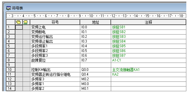
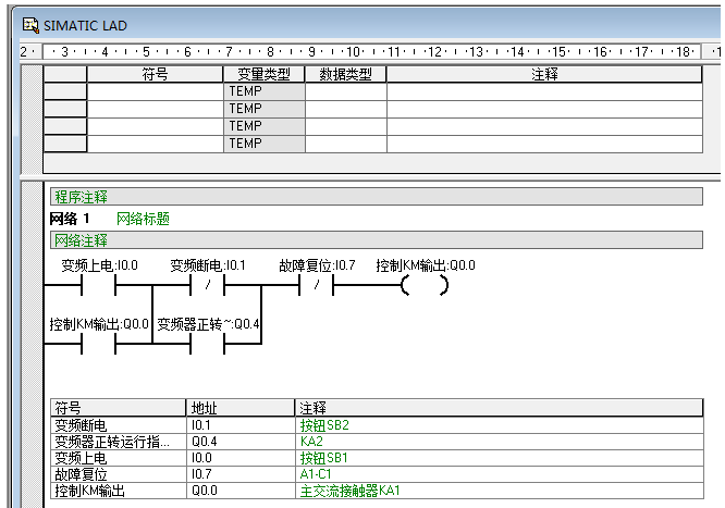
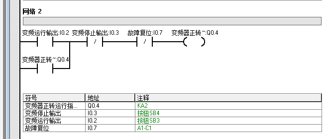
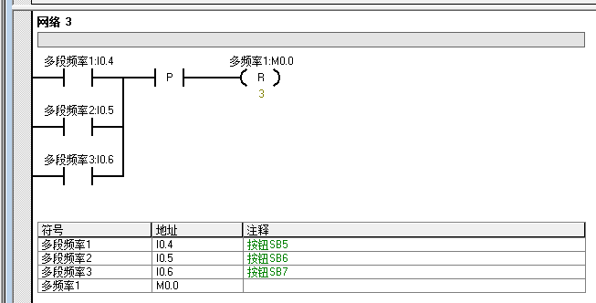
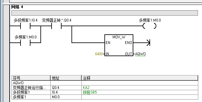
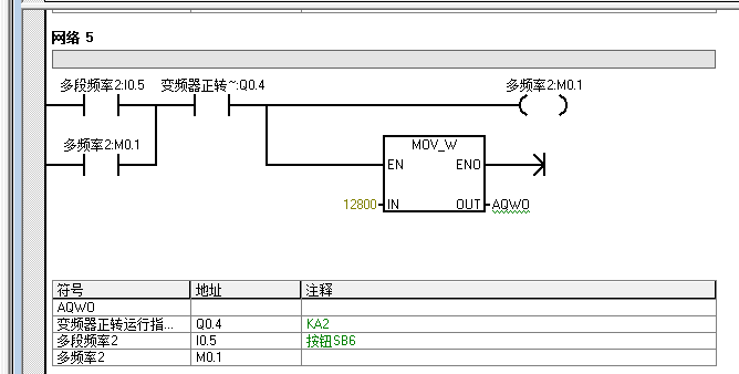
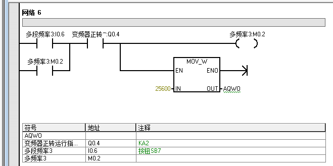 Principle Analysis:1: Frequency Inverter Closing1. Close the main power switch QF1, PLC control power QF3, and the frequency inverter input contactor control power QF2. The PLC converts the output voltage signal (0-10V) or current signal (4-20mA) into an intermediate variable (0-32000). In the program, the frequencies 10HZ, 20HZ, and 40HZ are converted to 6400, 12800, and 25600.2. Power on the frequency inverter, press the inverter closing button SB1, the I0.0 in the ladder diagram closes, the output relay Q0.0 is energized, the external contact Q0.0 connects with the 1L contact, the main AC contactor KM coil is energized, the main contact closes, and the frequency inverter is powered on. At the same time, the Q0.0 normally open contact in the ladder diagram closes to self-lock, ensuring KM remains energized.3. Set the frequency parameters according to the parameter table.2: PLC Control of Frequency OperationPress the frequency inverter run button SB3, the I0.2 in the ladder diagram closes, the output relay Q4.0 is energized, the external contact Q4.0 connects with the 2L, the frequency terminal STF and SD terminal close, and at the same time, the Q4.0 normally open contact closes to self-lock, preparing for multi-speed operation.3: Three-Speed Operation1. Press the frequency 1 button SB5, the I0.4 in the ladder diagram closes, the rising edge triggers and outputs, the internal relays M0.0, M0.1, M0.2 reset once, and all frequency outputs reset. At the same time, the internal relay M0.0 is energized, assigning frequency 1 to the PLC’s analog output, outputting 2V voltage to terminals 4 and 5 connected to the frequency inverter, which runs at a frequency of 10HZ.2. Press the frequency 2 button SB6, the I0.5 in the ladder diagram closes, the rising edge triggers and outputs, the internal relays M0.0, M0.1, M0.2 reset once, and all frequency outputs reset. At the same time, the internal relay M0.1 is energized, assigning frequency 2 to the PLC’s analog output, outputting 2V voltage to terminals 4 and 5 connected to the frequency inverter, which runs at a frequency of 20HZ.3. Press the frequency 3 button SB7, the I0.6 in the ladder diagram closes, the rising edge triggers and outputs, the internal relays M0.0, M0.1, M0.2 reset once, and all frequency outputs reset. At the same time, the internal relay M0.2 is energized, assigning frequency 3 to the PLC’s analog output, outputting 2V voltage to terminals 4 and 5 connected to the frequency inverter, which runs at a frequency of 40HZ.The frequency can be set arbitrarily, without needing to follow a sequence, because regardless of which speed is pressed, all frequencies will reset.Press the stop output button SB4, the I0.3 in the ladder diagram loses power, the output relay Q0.1 loses power, the frequency inverter external terminals STF and SD disconnect, and the frequency inverter decelerates according to Pr.8 deceleration time 1 to 0HZ before the motor stops running. The frequency inverter panel run indicator goes out, displaying 0.00HZ. All Q0.4 normally open contacts in the circuit disconnect, the output relays M0.0, M0.1, M0.2 stop output, and I0.1 releases self-lock.Frequency Inverter Power OffDuring the operation of the frequency inverter, pressing the frequency inverter power off button SB2 is ineffective. Only after the frequency inverter stops running, pressing the frequency power off button SB2, the I0.1 in the ladder diagram outputs relay Q0.0 loses power, the PLC output point Q0.0 disconnects from 1L, and the KM contactor loses power and releases. The frequency inverter control panel indicator light and information go out. The Q0.0 normally open contact disconnects, releasing self-lock.When a frequency inverter fault occurs, terminals A1 and C1 connect, the I0.7 in the circuit is energized, the output relays Q0.0 and Q0.4 lose power, and the PLC output points Q0.0, Q0.4 lose power; the contactor disconnects, and the frequency inverter stops output. If there are any errors, please point them out so we can improve together…
Disclaimer: This article is a network reprint or adaptation, and the copyright belongs to the original author. If there are any copyright issues, please contact for deletion!