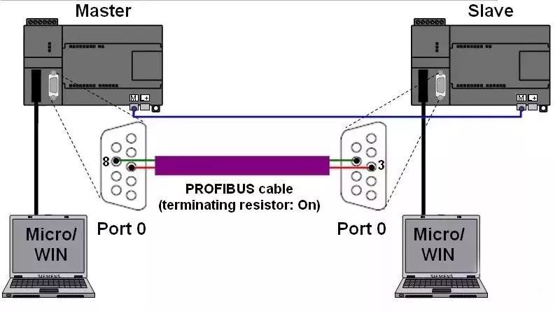
1. Hardware Setup The Modbus communication in the program is carried out between the 0 communication ports of two S7-200 CPUs (it is best for each CPU to have two communication ports). On the master side, communication can also be established using the corresponding library files “MBUS_CTRL_P1” and “MBUS_MSG_P1” through communication port 1. Communication port 1 connects to PG or PC using Micro/WIN, while the communication ports 0 of the two CPUs are connected via Profibus cable (the cable pin connections are 3, 3, 8, 8 -> see Figure 01). Additionally, it is necessary to ensure that the logical connections are made correctly.
2. Parameter Matching
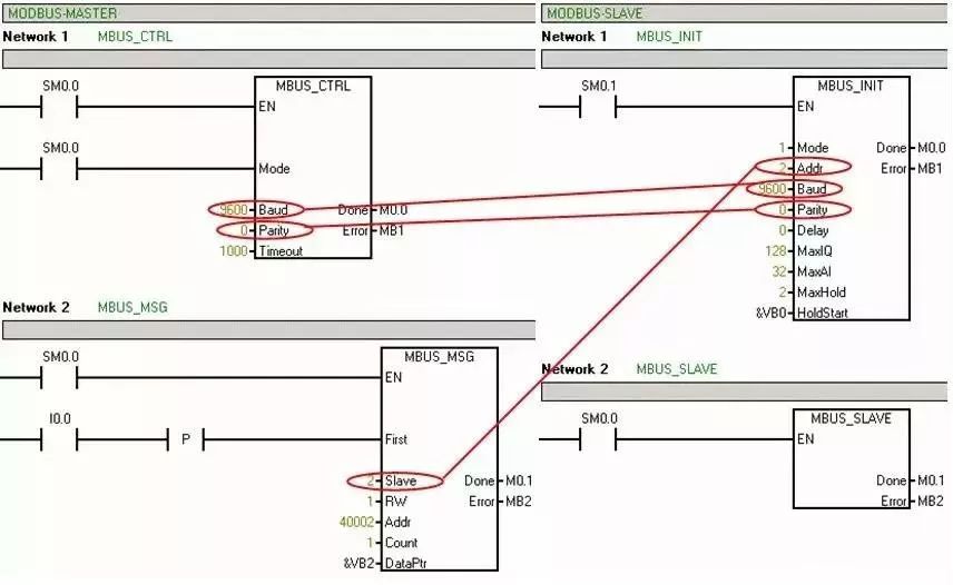
For MODBUS communication, the master side requires the program libraries “MBUS_CTRL” and “MBUS_MSG”, while the slave side requires the program libraries “MBUS_INIT” and “MBUS_SLAVE”. In Micro/WIN, you need to create a new project for both the master and slave, as shown in Figure 02. It is crucial to ensure that the parameters for “Baud” and “Parity” on the master and slave sides are consistent, and that the “Slave” address in the program block “MBUS_MSG” matches the “Addr” set in the program block “MBUS_INIT” (see Figure 02). The baud rate set for communication port 0 in the Micro/WIN “system block” is unrelated to the MODBUS protocol (“Mode” = “1”).
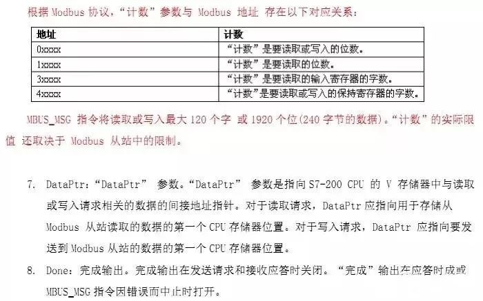
The table below lists the various parameter options and their meanings for the program block. Master MBUS_CTRL
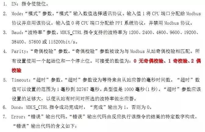

MBUS_MSG

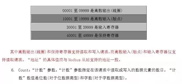

Slave MBUS_INIT
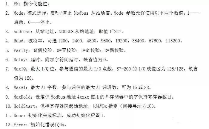
MBUS_SLAVE

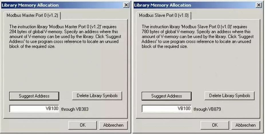
3. Library Storage Address After completing the project, you must define the storage address of the library in Micro/WIN. Once the storage area is defined, it must not be used by any other program under any circumstances (Master side: “DataPtr” + “Count” Slave side: “HoldStart” + “MaxHold”).
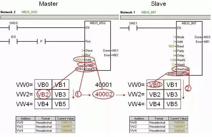
4. Transmission of Holding Register Values After downloading the program to the corresponding CPU, values can be assigned to the V storage area on the master side in the status table, and then the changes in values can be monitored on the slave side. When the I0.0 on the master side is enabled, the contents of VW2 are sent to the slave and written into the slave’s VW2. The transmission of holding register values is shown in Figure 04. The pointer “DataPtr” represents the starting address of the V area being read. The parameter “Count” specifies the number of words to be written to the address “Addr” = “4xxxx” (holding register). The corresponding V storage area variables will be written to the starting address of the holding register “Addr” = “40002” (“RW” = “1”). The holding register is transmitted in words and corresponds to the V area address of the slave. The pointer “HoldStart” specifies the initial address of the V storage area corresponding to the holding register starting address 40001. The target pointer for the slave’s V area can be calculated using the following formula: 2 * (Addr – 40001) + HoldStart = 2 * (40002 – 40001) + &VB0 = &VB2 Additionally, ensure that the data area to be written by the master side is included within the data area defined by “MaxHold”: MaxHold >= Addr – 40001 + Count = 40002 – 40001 + 1 = 2
End
 Looking here