01 Terminology Interpretation
Checksum:The checksum is derived from the previous data through some algorithm to verify the correctness of that data set.When code is input as data into a computer or other devices, input errors can easily occur. To reduce such input errors, coding experts have invented various checksum methods and set checksums based on these methods.
Common checks include: Checksum SUM, Byte XOR Check, Longitudinal Redundancy Check LRC, and Cyclic Redundancy Check CRC…
Discrete Input: Mainly used to read data from a single bit, such as the status of IO;
Coil: Switch output signal, mainly used to write a single bit of data, forming a paired operation with discrete inputs;
Input Register: Mainly used to read 16 bits, which is two bytes of data;
Holding Register: Mainly used to write 16 bits of data.
PLC: Programmable Logic Controller, a type of programmable memory that stores programs internally, executes logical operations, sequential control, timing, counting, and arithmetic operations, and controls various types of machinery or production processes through digital or analog input/output instructions.
Serial Communication: With the application of computer systems and the development of microcomputer networks, communication functionality has become increasingly important. The communication referred to here is the exchange of information between computers and the outside world. Therefore, communication includes information exchange between computers and external devices, as well as between computers. Since serial communication transmits information one bit at a time over a single transmission line, it requires fewer transmission lines and can utilize existing telephone networks for information transfer, making it particularly suitable for long-distance transmission. For those human-machine exchange devices and external devices like terminals, printers, logic analyzers, and disks that are not far from the computer, serial data exchange is also common. In real-time control and management, communication between CPUs in a hierarchical distributed control system is generally serial. Thus, the serial interface is a commonly used interface in microcomputer application systems. Many peripherals and computers communicate in a serial manner. The term serial communication refers to the information transfer method between peripherals and interface circuits, while the CPU and interface still operate in parallel.
Serial Port: A serial port is a very common communication protocol for devices on a computer, and should not be confused with the Universal Serial Bus (USB). Most computers contain two RS232-based serial ports. The serial port is also a common communication protocol for instruments and devices; many GPIB compatible devices also have RS-232 ports. Additionally, the serial port communication protocol can also be used to retrieve data from remote acquisition devices.
The concept of serial communication is very simple; the serial port sends and receives bytes bit by bit. Although it is slower than byte-wise parallel communication, the serial port can send data on one line while receiving data on another. It is simple and capable of long-distance communication. For example, when IEEE488 defines parallel communication, it states that the total length of device lines must not exceed 20 meters, and the length between any two devices must not exceed 2 meters; whereas for serial ports, the length can reach up to 1200 meters.
Typically, serial ports are used for the transmission of ASCII characters. Communication is accomplished using three lines: (1) ground line, (2) transmit, (3) receive. Since serial communication is asynchronous, the port can send data on one line while receiving data on another. Other lines are used for handshaking, but are not mandatory. The most important parameters of serial communication are baud rate, data bits, stop bits, and parity. For two ports communicating, these parameters must match:
a. Baud Rate: This is a parameter that measures the speed of communication. It indicates the number of bits transmitted per second. For example, 300 baud means sending 300 bits per second. When we mention clock cycles, we refer to the baud rate. For instance, if a protocol requires a baud rate of 4800, then the clock is 4800Hz. This means that the sampling rate of serial communication on the data line is 4800Hz. Typically, telephone lines have baud rates of 14400, 28800, and 36600. Baud rates can be much higher than these values, but baud rate is inversely proportional to distance. High baud rates are often used for communication between instruments that are very close together, a typical example being GPIB device communication. b. Data Bits: This is a parameter that measures the actual data bits in communication. When a computer sends a data packet, the actual data is not always 8 bits; the standard values are 5, 7, and 8 bits. How it is set depends on the information you want to transmit. For example, standard ASCII code is 0-127 (7 bits). The extended ASCII code is 0-255 (8 bits). If the data uses simple text (standard ASCII), then each data packet uses 7 bits of data. Each packet refers to a byte, which includes start/stop bits, data bits, and parity bits. Since the actual data bits depend on the selected communication protocol, the term ‘packet’ refers to any communication situation. c. Stop Bits: Used to indicate the last bit of a single packet. Typical values are 1, 1.5, and 2 bits. Since data is timed on the transmission line, and each device has its own clock, it is likely that there may be slight desynchronization between the two devices during communication. Therefore, stop bits not only indicate the end of transmission but also provide an opportunity for the computer to correct clock synchronization. The more stop bits are used, the greater the tolerance for clock desynchronization, but the data transmission rate also becomes slower. d. Parity Bit: A simple error-checking method in serial communication. There are four types of error-checking methods: even, odd, high, and low. Of course, having no parity bit is also acceptable. For even and odd parity cases, the serial port sets a parity bit (one bit after the data bits) to ensure that the transmitted data has an even or odd number of high bits. For example, if the data is 011, then for even parity, the parity bit is 0, ensuring that the number of logical high bits is even. If it is odd parity, the parity bit is 1, resulting in three logical high bits. High and low bits do not actually check the data; they simply set logical high or low checks. This allows the receiving device to know the state of a bit and have an opportunity to determine whether noise has interfered with communication or whether the transmission and reception of data are out of sync.

02 Background
In 1971, Modicon first introduced the Modbus protocol, giving birth to Modbus RTU and Modbus ASCII. Later, Schneider Electric acquired Modicon and launched the Modbus TCP protocol in 1997. In 2004, the Chinese National Standards Committee officially adopted Modbus as a national standard, marking the beginning of Modbus’s contribution to industrial communication in China.
Through this protocol, controllers can communicate with each other, and controllers can communicate with other devices over a network. The Modbus protocol is characterized by being standard, open, supporting multiple electrical interfaces, having a simple and compact data frame format, large data transmission volume, and good real-time performance, and has been widely used in industrial control systems, becoming a general industrial standard. An in-depth analysis of the implementation principles and security of the Modbus protocol is of significant practical importance for enhancing the security of industrial control systems. Modbus RTU and Modbus ASCII are mainly used in serial communication, while Modbus TCP is commonly used in Ethernet communication. Today, Modbus has become the standard communication protocol in the industrial field and is now a very commonly used connection method between industrial electronic devices.
03 Protocol Principles
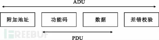
Modbus uses a simple Master and Slave protocol (client/server protocol) for communication. The client acts as the master and sends requests to the server; the server (slave) receives the request, analyzes it, and responds. The communication frame used is called the Application Data Unit (ADU), which includes the communication address segment, function code segment, data segment, and checksum segment, as shown in the figure below:
In general use, monitoring systems (HMI) are usually the Master, while PLCs, electric meters, instruments, etc., are the Slaves. The HMI system continuously polls various relay and register values from the Slaves, displaying and processing them for various logical calculations and control adjustments.
Here, the function code segment and data segment combined are referred to as the Protocol Data Unit (PDU). The function code segment occupies one byte, with a value range of 1-255, where 128-255 are reserved for abnormal message response packets. The values 1-127 are function code numbers, with 65-72 and 100-110 being user-defined codes.
04 Transmission Methods
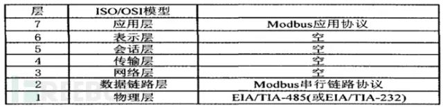
The Modbus protocol is an application layer message transmission protocol that includes three types of messages: ASCII, RTU, and TCP. The protocol itself does not define the physical layer; it only defines the message structure that controllers can recognize and use, regardless of the network used for communication.
When using the Modbus protocol for serial transmission, either RTU or ASCII mode can be selected, and it specifies message, data structure, command, and response methods, requiring data verification. The ASCII mode uses LRC checksum, while the RTU mode uses 16-bit CRC checksum. When transmitted over Ethernet, TCP is used, and this mode does not use checksums because the TCP protocol is a reliable, connection-oriented protocol.
05 Differences Between Modbus RTU and Modbus ASCII
Modbus is an application layer protocol that defines data units (ADU) independent of the underlying network, allowing communication over Ethernet (TCP/IP) or serial links (RS232, RS485, etc.) (Ethernet ADU and serial ADU differ slightly). In serial links, the Modbus protocol has two transmission modes—ASCII mode and RTU mode. ASCII is the abbreviation for American Standard Code for Information Interchange, while RTU stands for Remote Terminal Unit.
First, let’s take a look at how Modbus works.
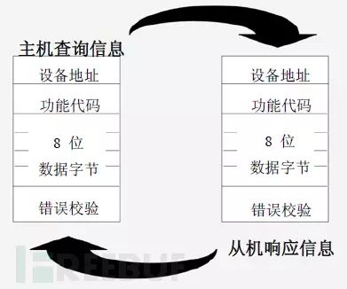
Modbus employs a Master-Slave communication mode, where only the Master device can initiate transmission, and the Slave device responds based on the Master’s request. Typical Master devices include field instruments and display panels, while typical Slave devices are Programmable Logic Controllers (PLCs).
In Master-Slave communication over serial links, a Modbus Master device can connect to one or N (up to 247) Slave devices. Communication between Master and Slave devices includes unicast and broadcast modes.
In broadcast mode, the Modbus Master can simultaneously send requests to multiple Slave devices (device address 0 is used for broadcast mode), and Slave devices do not respond to broadcast requests.
In unicast mode, the Master sends a request to a specific Slave device (each Modbus Slave has a unique address), and the request message frame will contain function codes and data, such as function code “01” used to read the status of discrete coils. Upon receiving the request, the Slave responds and feeds back the message to the Master.
In communication between Master and Slave devices, either ASCII mode or RTU mode can be used.
In ASCII (American Standard Code for Information Interchange) transmission mode, the message frame begins with an English colon (“:”, ASCII 3A Hex) and ends with a carriage return and line feed (CRLF, ASCII 0D and 0A Hex). The allowed character set for transmission is hexadecimal 0-9 and A-F; the Slave devices in the network monitor the transmission path for the presence of the English colon (“:”). If present, they decode the message frame and check if the address in the message matches their own address. If it matches, they receive the data; if not, they ignore it.

In ASCII mode, each 8-bit byte is split into two ASCII characters for transmission. For example, the hexadecimal number 0xAF would be split into ASCII characters “A” and “F” for transmission, which doubles the amount of characters sent compared to RTU. The advantage of ASCII mode is that it allows for a gap of up to 1 second between characters without causing communication failure. This mode uses Longitudinal Redundancy Check (LRC) for error checking.
When the controller is set to communicate over the Modbus network in RTU mode, each 8-bit byte in the message contains two 4-bit hexadecimal characters, and this mode has no start and end markers. Its advantage is that it can transmit more data at the same baud rate.
In RTU (Remote Terminal Unit) mode, each byte can transmit two hexadecimal characters, for example, the hexadecimal number 0xAF is sent directly as hexadecimal 0xAF (binary: 10101111), thus its transmission density is twice that of ASCII mode; RTU mode uses Cyclic Redundancy Check (CRC), and the summary of RTU mode is as follows:
The specific format is shown in the figure below.

06 Modbus TCP and Its Considerations
6.1 Master and Slave, Server and Client
[In the Modbus protocol]
The master sends Modbus requests, and the slave returns responses based on the request content. In the Modbus protocol, the master is always the active party, while the slave is always the passive party.
[In network applications]
In network applications, there are clients and servers; a client (such as a browser) sends requests to the server, which returns content (such as HTML text) to the client.
[In Modbus TCP]
The master is the client, while the slave is the server. Do not think that the server is more important; the master is also important, so the master is the server.
6.2 Can There Be Multiple Masters?
From the previous analysis, since the master is the client, Modbus TCP supports multiple masters, and there can be multiple masters and slaves in a local area network. The connection capability of the slaves (the number of hosts that can connect) is determined by the maximum number of TCP connections of uIP.
6.3 Brief Overview of Modbus TCP Protocol
Modbus TCP is essentially the same as Modbus RTU, but there are some differences.
a. The slave address becomes less important and is often ignored. In a sense, the slave address is replaced by the IP address.
b. CRC check becomes less important and can even be ignored. Since the TCP packet already has a checksum, Modbus TCP simply eliminates the CRC check to avoid redundancy.
The TCP mode was developed to ensure smooth transmission of Modbus data over Ethernet, using TCP port 502. In terms of physical layer, data link layer, network layer, and transport layer, it is all based on the TCP protocol, only at the application layer is the Modbus protocol modified and encapsulated; the receiving end unpacks the TCP packet to retrieve the original Modbus frame, then parses it according to Modbus protocol specifications and repackages the returned data packet into the TCP protocol to send back to the sender. The data format for transmission differs from that of serial links, as TCP mode removes additional addresses and checksums while adding a message header, with the specific format shown in the figure below.
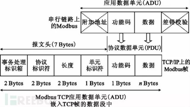
In Modbus TCP, there is an MBAP header that includes the following parts:
| Field | Length | Description | Client | Server |
|---|---|---|---|---|
| Transmission Flag | 2 bytes | Sequence number during MODBUS request and response transmission | Generated by the client | Copied by the server in the response |
| Protocol Flag | 2 bytes | Modbus protocol defaults to 0 | Generated by the client | Copied by the server in the response |
| Length | 2 bytes | Length of the remaining part | Generated by the client | Generated by the server in the response |
| Unit Flag | 1 byte | Slave flag (slave address) | Generated by the client | Copied by the server in the response |
[Note]
[1] The transmission flag can be understood as a sequence number to prevent MODBUS TCP communication misalignment, such as a later response arriving at the host before an earlier response.
[2] The unit flag can be understood as the slave address, which is no longer important.
6.4 Relationship Between Modbus TCP and TCP IP
Modbus TCP can be understood as an application layer protocol that occurs over TCP. Since it is based on the TCP protocol, a complete MODBUS TCP message must include the TCP header, IP header, and Ethernet header.
07 Function Code Role
The client that initiates the Modbus transaction creates the Modbus application data unit. The function code (in the PDU) indicates to the server what operation will be executed.
One byte encodes the function code field of the Modbus data unit. The valid range is decimal 1-255 (128-255 are reserved for abnormal responses). When a message is sent from the client to the server, the function code field indicates which operation will be performed by the server.
The data field of the message sent from the client to the server includes additional information that the server uses to perform the operation defined by the function code. This field also includes addresses of discrete items and registers, the number of items to be processed, and the actual number of data bytes in the field.
In certain requests, the data field may be absent, in which case the server does not need any additional information. The function code simply indicates the operation.
Types of Function Codes
Function codes are mainly divided into valid function codes, abnormal function codes, and error function codes.
If there are no errors related to the requested Modbus function in a correctly received Modbus ADU, the response data from the server to the client will contain the normal function code from the request. If there are errors related to the requested Modbus function, the response data will contain an abnormal code and an error code.
For example, the client can read the on/off status of a set of discrete outputs or inputs, or the user can read/write a set of register data content. When the server responds to the client, it uses the function code field to indicate a normal (no error) response or an error (abnormal response). For a normal response, the server only responds with the original function code, as shown in the figure below:
For an abnormal response, the server returns a code equivalent to that of the client, setting the most significant bit of that original function code to logical 1, and adds the abnormal code and error code to notify the client of the reason for the abnormality. As shown in the figure below:
Valid Function Codes
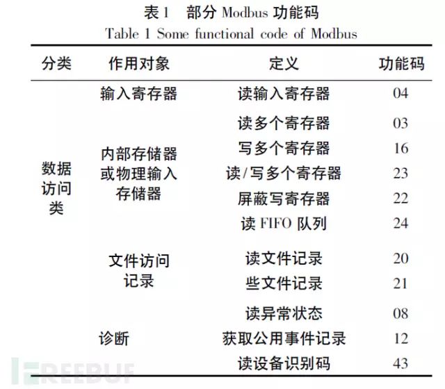
There are more than twenty valid function codes, but generally, the most commonly used are 1, 2, 3, 4, 5, 6, 15, 16, as well as the two special use codes 20, 21, which are General Reference Registers, and most Modbus devices do not provide this Register. The main control data on PLCs includes the following four types. These eight function codes are used to process this control data, with detailed explanations as follows:
Control Data Four Types:
DI: Digital Input (discrete input), one address one data bit, users can only read its status and cannot modify it. Represented by one bit as On/Off, used to record the status of control signal inputs, such as switches, contact points, motor operation, limit switches, etc. In PLCs, it is referred to as Input relay, input coil, etc.
DO: Digital Output (coil output), one address one data bit, users can set, reset, and read back the status. Represented by one bit as On/Off, used to output control signals to activate or stop motors, alarms, lights, etc. In PLCs, it is referred to as Output relay, Output coil, etc.
AI: Analog Input (input register), one address 16-bit data, users can only read and cannot modify it, represented by a 16 bits integer to record the value of control signal inputs, such as temperature, flow, material amount, speed, rotation speed, valve opening, liquid level, weight, etc. In PLCs, it is referred to as Input register.
AO: Analog Output (holding register), one address 16-bit data, users can write and read back, represented by a 16 bits integer to output the value of control signals, such as temperature, flow, speed, rotation speed, valve opening, feed amount, etc. In PLCs, it is referred to as Output register, Holding register.
08 Security Analysis of the Modbus Protocol
The Modbus protocol is a typical industrial control network protocol, and studying its security is of great importance for enhancing the security of industrial control networks. Generally speaking, security issues with protocols can be divided into two types: one type is security issues caused by the protocol’s own design and description; the other type is security issues arising from incorrect implementation of the protocol. The Modbus protocol also has both of these issues.
8.1 Inherent Issues of the Modbus Protocol
Most industrial control protocols were designed primarily to consider functionality, efficiency, and reliability, without considering security issues. The Modbus protocol is no exception, even though it has become a de facto industrial standard. From the previous principle analysis, we can see its inherent security issues: lack of authentication, authorization, encryption, and issues with function code abuse.
(1) Lack of Authentication
The purpose of authentication is to ensure that the received information comes from legitimate users; unauthorized users sending control commands to devices will not be executed. There are no relevant definitions regarding authentication in the Modbus protocol communication process; an attacker only needs to find a legitimate address to establish a Modbus communication session using function codes, thereby disrupting the entire or part of the control process.
(2) Lack of Authorization
Authorization ensures that different privileged operations must be performed by authenticated users with different permissions, which greatly reduces the probability of operational errors and internal attacks. Currently, the Modbus protocol does not have a role-based access control mechanism, does not categorize users, and does not classify user permissions, which allows any user to execute any function.
(3) Lack of Encryption
Encryption ensures that the information between both parties during communication is not illegally obtained by third parties. In the Modbus protocol communication process, addresses and commands are all transmitted in plaintext, making it easy for attackers to capture and analyze the data, providing convenience for attackers.
(4) Function Code Abuse
Function codes are an important part of the Modbus protocol, and almost all communications include function codes. Currently, function code abuse is a major factor leading to anomalies in Modbus networks. For example, illegal message lengths, short-cycle useless commands, incorrect message lengths, delayed confirmation of abnormal codes, etc., can all lead to denial of service attacks.
8.2 Issues Arising from Protocol Implementation
Although the Modbus protocol has been widely adopted, developers implementing specific industrial control systems often lack security knowledge or fail to recognize security issues. This leads to various security vulnerabilities in systems using the Modbus protocol.
(1) Design Security Issues
Developers of Modbus systems focus primarily on functional implementation issues, and security issues are rarely considered during design. Design security refers to sufficiently considering security during design to address various anomalies and illegal operations that may occur in Modbus systems. For instance, during communication, if a certain node is maliciously controlled to send illegal data, the identification and handling of such data need to be considered.
(2) Buffer Overflow Vulnerabilities
Buffer overflow refers to filling data into a buffer beyond its capacity, leading to overflow data overwriting legitimate data. This is the most common and dangerous vulnerability in software development, which can cause system crashes or be exploited by attackers to gain control of the system. Most developers of Modbus systems lack security development knowledge, which can lead to many buffer overflow vulnerabilities that, if exploited by malicious actors, can have severe consequences.
(3) Modbus TCP Security Issues
Currently, the Modbus protocol can be implemented on general computers and general operating systems, running over TCP/IP to meet developmental needs. Thus, the inherent security issues of the TCP/IP protocol will inevitably affect the security of industrial control networks. Common attack methods in the IP internet, such as unauthorized network data acquisition, man-in-the-middle attacks, denial of service, IP spoofing, and viruses/trojans, will all impact the security of Modbus systems.
8.3 Security Recommendations
Currently, the security measures taken by Modbus systems are generally insufficient. Here, some security recommendations are proposed based on information security industry research and the specific security issues of industrial control systems, which can effectively reduce the threats faced by industrial control systems.
(1) Start from the Source
Vulnerabilities in industrial control networks largely stem from issues that arise during implementation. If control begins at the source, incorporating security measures throughout the entire lifecycle of the Modbus system—from requirement design, development, internal testing, to deployment—can significantly eliminate security vulnerabilities and reduce the overall security risks of the Modbus system.
(2) Anomaly Behavior Detection
Anomalous behavior represents potential threats, regardless of whether there are attackers. Therefore, developing specialized anomaly detection devices for Modbus systems can greatly enhance the security of industrial control networks. For Modbus systems, it is essential to analyze the various operational behaviors, describing behaviors based on a six-tuple model of “subject, location, time, access method, operation, object”; subsequently analyzing whether the behavior is anomalous; and ultimately deciding whether to record or alert.
(3) Security Auditing
Security auditing for Modbus involves deep decoding and analysis of protocol data, recording key information such as the time, location, operator, and operational behavior, enabling security auditing logs and auditing capabilities for Modbus systems, thus providing traceability for security incidents.
(4) Use of Network Security Devices
Utilizing intrusion prevention and firewall network security devices. Firewalls are serial devices that, through configuration, only allow specific addresses to access the server, preventing external addresses from accessing the Modbus server, effectively preventing external intrusions; intrusion prevention devices can analyze the specific operational content of the Modbus protocol, effectively detecting and blocking abnormal operations and various penetration attacks from both internal and external sources, providing protection for the internal network.