Recently, an old student asked about the design of the Siemens SMART200 PLC servo motor and electric hoist control program. I will summarize and organize the information here for interested students!
Project Overview
This project originates from the practical need for automated control of a single-arm crane, aiming to build a reliable control system using the Siemens SMART200 PLC to achieve precise coordinated control of the servo motor and electric hoist. The core control objects involved in the project include one Li Chuan B2 2 kW servo motor and one electric hoist, where the servo motor needs to achieve precise positioning control for forward/reverse rotation to a specified position (both equipped with limit protection mechanisms), while the electric hoist needs to implement point-to-point operation for upward and downward travel (with limit protection for upward travel).
Core Design Objectives: The focus is on precise positioning of the servo motor and safe point operation of the electric hoist, ensuring position control accuracy through the motion control commands of the SMART200 PLC (such as pulse output and position feedback closed-loop control), while meeting key constraints in industrial safety standards, including highest priority for emergency stop signals and hard interlock for limit protection, eliminating the risk of mechanical overrun due to program logic failure.
The control system design must strictly adhere to industrial automation standards, using ladder diagram programming to develop a complete control program, including detailed program comments to ensure maintainability. By integrating the motion control function modules of the SMART200 PLC (such as position control commands and speed mode switching logic), the reliability of the servo motor position closed-loop control is achieved, and through dual guarantees of electrical circuit design and program logic, the safety and responsiveness of the electric hoist’s point operation are ensured.
System Hardware Configuration
The hardware configuration of this system is centered around the Siemens SMART200 PLC, paired with the Li Chuan B2 series servo drive system and a frequency-controlled electric hoist, forming an integrated automation solution that combines driving, control, and execution. The hardware selection fully considers equipment compatibility, reliability in industrial environments, and control accuracy requirements, with the specific configuration as follows:
Hardware Selection Basis
The core hardware of the system includes Siemens SMART200 ST30 PLC (24 inputs/16 outputs), Li Chuan B2 series servo system (driver model LCDB2-203002-LB1332, compatible with 2kW servo motor) and frequency contactor controlled electric hoist. The selection basis is as follows:
- PLC Selection: The Siemens SMART200 ST30 features a compact structure and rich I/O interfaces, with 24 digital inputs meeting the detection needs for limit signals, remote control commands, etc., and 16 outputs supporting servo drive and contactor control, suitable for logic and motion control of medium and small automation devices.
- Servo System Selection: Li Chuan, as a professional EtherCAT servo manufacturer, has its B2 series drivers adopting a DSP+FPGA architecture, with fast data processing speed, integrating industrial-grade intelligent power modules (IPM), and a capacity one level higher than similar products. The 2kW model has an overload capacity of 2.5 times, capable of handling the impact load during the start-stop phase of the electric hoist. The matching motor is an 80mm flange series AC 220V servo motor, with CE certification and a 17-bit absolute encoder, ensuring precise position control.
- Electric Hoist Selection: The frequency contactor control mode is adopted, combined with upper and lower limit protection, suitable for medium and low load lifting scenarios, directly linked to the PLC output module for safe start-stop operations.
Servo System Compatibility Analysis
The compatibility of the Li Chuan B2 series driver (LCDB2-203002-LB1332) with the servo motor is reflected in three aspects: electrical parameters, control performance, and environmental adaptability:
- Electrical Parameter Matching: The driver supports three-phase 220V power supply, with output current matching the motor’s rated current. Models below 1.5kW have an overload capacity of 3 times, while the 2kW model reaches 2.5 times, capable of withstanding dynamic load fluctuations of the electric hoist. The motor adopts a 5-pair pole design, with a rated speed of 1500rpm, providing smooth torque output, meeting the low-speed high-torque requirements of lifting equipment.
- Control Mode Compatibility
- : The driver supports pulse + direction (differential signal) control mode, with a maximum pulse frequency of 500kHz, matching the high-speed pulse output port of the Siemens SMART200 PLC, enabling precise speed and position control. The encoder uses a 2500-line incremental feedback, communicating in real-time with the motor through the CN2 interface, forming a closed-loop control.
- Environmental Adaptability: The driver operates in an environmental temperature range of 0-55℃ (no frost), with humidity below 90%RH (no condensation), and vibration resistance of 0.5G (4.9m/s²), suitable for installation in industrial control cabinets; the motor has an IP54 protection level, adapting to dusty environments.
I/O Distribution Table
The system I/O signal distribution is shown in the table below, covering servo control, electric hoist operation, and safety limit functions:
| Address | Signal Description | Contact Type | Device Connection Object |
|---|---|---|---|
| I0.0 | Servo Left Limit Switch | Normally Open | Mechanical limit on the left side of the servo motor |
| I0.1 | Servo Right Limit Switch | Normally Open | Mechanical limit on the right side of the servo motor |
| I0.2 | Electric Hoist Upper Limit Switch | Normally Open | Top limit of the electric hoist lifting mechanism |
| I0.3 | Electric Hoist Lower Limit Switch | Normally Open | Bottom limit of the electric hoist lifting mechanism |
| I0.4 | Crane Remote Control Start Button | Normally Open | Start signal after remote control emergency stop reset |
| I0.5 | Crane Remote Control Stop Button | Normally Closed | Remote control emergency stop or stop command |
| Q0.0 | Servo Drive Enable Signal | Output | Drive CN1 interface SERVO-ON pin |
| Q0.1 | Servo Forward Command | Output | Drive CN1 interface FORWARD pin |
| Q0.2 | Servo Reverse Command | Output | Drive CN1 interface REVERSE pin |
| Q0.3 | Electric Hoist Ascending Contactor Coil | Output | Electric hoist main circuit ascending contactor |
| Q0.4 | Electric Hoist Descending Contactor Coil | Output | Electric hoist main circuit descending contactor |
| Q0.5 | System Fault Alarm Indicator | Output | Control cabinet fault indicator LED |
Hardware Interface Relationships
PLC and Servo Drive Interface
- Main Circuit: Three-phase power lines (R, S, T) are connected to the driver power input through an NFB circuit breaker, and the motor power lines (U, V, W) connect to the driver output to supply power to the motor.
- Control Circuit: The PLC digital output ports (Q0.0-Q0.2) are connected to the driver CN1 interface via shielded cables, where Q0.0 connects to SERVO-ON (driver enable), Q0.1 connects to FORWARD (forward command), and Q0.2 connects to REVERSE (reverse command); the encoder feedback line connects to the motor through the CN2 interface, forming a closed-loop control.
PLC and Electric Hoist Interface
The PLC output ports (Q0.3-Q0.4) control the electric hoist frequency contactor coils through relays, achieving ascending/descending actions. The contactor main contacts connect to the three-phase power supply and the electric hoist motor, with the control circuit in series with the upper and lower limit switches (I0.2-I0.3) normally closed contacts, forming a hardware safety interlock.
Key Interface Precautions
- The main power supply of the servo drive must be equipped with an NFB circuit breaker, with a rated current selected at 1.5 times the rated current of the driver;
- The control circuit shielded cable must be grounded at one end, with a length not exceeding 10m to avoid electromagnetic interference;
- The limit switches must use mechanical contact types, with an action response time <10ms to ensure emergency stop reliability.
The system hardware configuration achieves organic integration of the control layer (PLC), drive layer (servo system), and execution layer (electric hoist) through modular design, balancing control accuracy and operational safety, meeting the lifting and positioning needs in industrial automation scenarios.
Control Logic Design
Servo Motor Control Logic
Control Method and Signal Interaction
The servo motor adoptsIGBT PWM control sine wave current driving method, achieving precise control of position and speed through pulse signals. The control signal system includes three core elements: pulse signal (Pulse) for setting the motor rotation angle and speed, direction signal (Direction) for controlling the rotation direction (high level for forward, low level for reverse), and enable signal (Enable) for motor start-stop. The pulse input interface supports three types: direction + pulse, CW/CCW, and quadrature encoding, with a maximum pulse frequency of 500kHz, ensuring high-speed and high-precision control.
Forward and Reverse Triggering and Position Closed-Loop Control
Trigger Conditions: The forward/reverse action of the servo motor is directly triggered by the button signal from the remote control. After the PLC receives the button signal, it generates position closed-loop control commands through theTO_Position command, achieving precise movement of the motor to the specified position. The position control mode requires pre-setting driver parameters (e.g., PA01=0000), with the PLC sending position commands through differential pulse signals, while combining encoder feedback to form a three-loop control system—the innermost loop is the current loop (adjusting torque through Hall current detection), the middle loop is the speed loop (PID adjustment based on encoder signals), and the outer loop is the position loop (output as the speed loop set value), ensuring positioning accuracy.
Limit Protection Mechanism
The limit protection adoptshardware priority cut-off design, directly connecting the left/right hard limit signals (P-OT/forward prohibition, N-OT/reverse prohibition) to the PLC digital input ports. When the motor moves to the limit position, the limit switch triggers a signal that immediately interrupts the current control process through the PLC input module, prioritizing the cut-off of the servo output (e.g., /S-ON signal), forcibly stopping the motor to avoid mechanical overload. This mechanism is independent of the position control logic, with a response priority higher than the remote control commands, forming a dual safety guarantee.
Origin Return Logic
The origin return function is triggered by the left limit signal for mechanical origin calibration. The specific process is: the PLC controls the motor to reverse at low speed until the left limit switch is triggered. After triggering, the motor briefly rotates forward to leave the limit area, then reverses again at a very low speed until the limit signal reappears, at which point the encoder is zeroed and the current position is recorded as the mechanical origin. After calibration, the system supports a “zero to one back and forth” origin verification action to ensure the long-term stability of the origin position.
Core Points of Control Logic
- Trigger: Remote control button signal → PLC output direction/pulse signal
- Closed-loop: TO_Position command + encoder feedback (three-loop PID adjustment)
- Protection: Hard limit signal prioritizes cut-off of servo enable (S-ON)
- Calibration: Left limit trigger → low-speed seeking zero → encoder zeroing
Servo Control Flowchart Planning
The servo motor control flowchart must include the following logical nodes:
- Initialization Phase: Driver parameter configuration (PA01=0000), servo enable (S-ON signal set);
- Command Reception: The PLC continuously detects the status of the remote control forward/reverse buttons;
- Position Control: TO_Position command generates a pulse sequence, driving the motor to the target position;
- Limit Monitoring: Left/right limit signals are continuously fed into the PLC, immediately cutting off output when triggered;
- Origin Return: After the left limit signal is triggered, execute the seeking zero process to complete mechanical origin calibration;
- Status Feedback: Real-time updates of motor position through encoder signals, achieving closed-loop adjustment.
The flowchart must clearly display the logical relationships of each node, especially the interruption and reset mechanisms of limit protection and origin return on the main control flow.
The servo control subprogram will modularize the above logic, including origin return module, forward/reverse position control module, and limit protection module, achieving seamless connection and priority scheduling of each function through the PLC program.
Electric Hoist Control Logic
The electric hoist control logic design focuses onpoint control method, achieving safe and reliable operational control through remote control signals and hardware interlock mechanisms. Its control logic mainly includes point signal interaction, limit protection interlock, and program logic integration, with specific designs as follows:
Point Signal and Output Contactor Logic Relationship
The action control of the electric hoist relies on the normally open contact signal from the remote control, adoptingpoint control logic (press to act, release to stop). When the remote control sends a point signal (e.g., the ascending or descending button is pressed), the normally open contact closes, triggering the corresponding output contactor coil to energize, driving the motor to operate; when the button is released, the contact opens, the contactor coil loses power, and the motor immediately stops. This logic relationship ensures the immediacy and controllability of the operation, avoiding the risk of unintended continuous action.
Core Logic Relationship: The relationship between the remote control button status and the output contactor is as follows → Button closed → Output contactor energized (motor running) → Button released → Output contactor cut off (motor stops)
Limit Protection Hard Interlock Design
To prevent the electric hoist from operating beyond the mechanical travel range, the system has set upupper/lower limit protection mechanisms. The upper limit signal adopts a normally closed contact form, connected in series to the ascending control circuit, forming a hard interlock protection: when the hook rises to trigger the upper limit switch, the normally closed contact opens, directly cutting off the control circuit of the ascending contactor, forcibly stopping the ascending action; the lower limit protection logic is similar, achieving the same through normally closed contacts in the descending control circuit. This hard interlock design is independent of software control, enhancing the reliability of safety protection.
Control Program Logic Integration
The electric hoist control subprogram needs to integrate the above core functions, specifically including:
- Ascending/Descending Point Control Logic: The PLC program detects the status of the remote control contact signals, controlling the corresponding contactor output in real-time;
- Limit Interlock Logic: Further strengthening limit protection at the program level, when a limit signal is detected, not only is the output cut off through hardware, but the control signal in the software for the corresponding direction is also locked to prevent misoperation;
- Signal Filtering Processing: To address potential interference from the remote control wireless signals, the program must include signal debounce processing to ensure the accuracy of control commands.
Control Timing Diagram Design Points
A “Electric Hoist Point Control Timing Diagram” must be drawn to visually display the signal interaction process, and the timing diagram should include the following key elements:
- The horizontal axis is the time axis, and the vertical axis labels the remote control point signal (up/down), upper limit signal, ascending contactor output, and descending contactor output;
- Show the delay in output contactor engagement and disconnection response time when the point signal is triggered (button pressed);
- Reflect the forced cut-off process of the ascending contactor output when the upper limit signal is triggered (normally closed contact opens);
- Label the time parameters of signal state changes (such as contactor engagement time, limit signal response time), providing a basis for setting delay parameters in program design.
Through the above logic design, the electric hoist control system achieves a balance between operational convenience and operational safety, meeting the precise control requirements for material lifting in industrial scenarios.
Safety Protection Logic
The safety protection logic is the core guarantee for the reliable operation of the Siemens SMART200 PLC servo motor and electric hoist control system, requiring the construction of a hierarchical logic tree to achieve priority processing of key signals such as emergency stop, limit, and fault, while combining hardware protection measures to form a complete protection system.
Emergency Stop Protection Mechanism
The emergency stop signal adoptsnormally closed contact design, connected to the PLC digital input module (e.g., terminal I1.1), maintaining an ON state during normal operation, and when triggered, the signal switches to OFF and immediately cuts off the servo enable and electric hoist contactor output. In program design, the emergency stop signal must be treated as the highest priority interrupt (e.g., INT0), ensuring that all output channels, including the servo driver enable signal and electric hoist forward/reverse contactor coil power, are cut off without delay when triggered.
Limit Protection Logic
The upper/lower limit travel switches (LSP/LSN) also adopt normally closed contact configuration, maintaining an ON state under normal conditions, and when the mechanical structure reaches the limit position, the contacts open. The limit signal has a higher priority than the control signal, and must be implemented in the PLC program through logical interlocking: when the limit signal is triggered, regardless of the current control instruction (e.g., ascending/descending button) status, the corresponding direction’s drive output must be forcibly cut off to prevent mechanical overrun damage.
Servo System Safety Protection
The servo driver must integrate multiple electrical protection functions, including overcurrent, overvoltage, undervoltage, overload, overspeed, regenerative braking faults, and encoder feedback errors. Its fault alarm terminal (ALM) is normally in the ON state, switching to OFF during abnormal conditions, requiring real-time monitoring through the PLC program and triggering alarm output (e.g., terminal Q0.5). Hardware installation must meet the following requirements: the driver PE terminal must be reliably connected to the control cabinet protective ground, the motor and regenerative braking resistor must be placed in a clean, dry environment free of corrosive gases, and an NFB circuit breaker must be connected in series between the main power supply and the driver to achieve overload and short-circuit protection.
Key Hardware Protection Measures
Hardware Wiring Safety Points
- The servo driver protection grounding PE terminal must be directly connected to the control cabinet PE bar, with a grounding wire cross-section ≥2.5mm² and single-point grounding.
- The direction of the freewheeling diode in parallel with the output load (e.g., contactor coil) must not be reversed, otherwise, it will lead to failure of the driver’s internal protection circuit.
- The fault alarm terminal (ALM) connection to the PLC input must use shielded cables to avoid electromagnetic interference causing false triggering.
Safety Logic Hierarchical Relationship
The system must construct a three-level protection logic tree: Level one is the emergency stop total protection, which cuts off all power outputs when triggered; Level two is limit protection, which independently cuts off the corresponding direction of motion by axis; Level three is the internal protection of the servo driver, which feeds back overcurrent, overvoltage, and other fault states through the ALM signal. The priority of the three is from high to low: emergency stop signal > limit signal > control signal. A “safety protection logic diagram” should be planned and drawn to visually display the signal flow, where the emergency stop and limit signals are connected in series through “AND gate” logic to control the servo enable loop, ensuring that when any protection signal is triggered, the system immediately enters a safe state.
The servo system must also be configured with an alarm reset signal interface. After the fault is cleared, the PLC program sends a reset command to restore normal operation, ensuring that the emergency stop and limit signals have returned to the ON state before resetting.
PLC Program Implementation
Program Structure Design
This system control program adopts amodular architecture design, with the main program implementing core scheduling and resource allocation, and each functional subprogram independently encapsulating control logic, forming a clear and hierarchical program system. This architecture not only enhances the maintainability and reusability of the code but also facilitates troubleshooting and functional expansion.
Main Program (OB1) Core Functions
The main program serves as the control hub of the system, undertaking two key responsibilities:
- Initialization Management: By calling the initialization subprogram (SBR0), it completes parameter configuration after power-up, I/O port initialization, and status variable reset, ensuring that each module is in a ready state;
- Module Scheduling: According to the control cycle, it sequentially calls servo control, electric hoist control, and alarm processing functional modules, and responds to emergency stop interrupts (INT0), achieving real-time task scheduling and emergency state handling.
Functional Subprogram Design
Each subprogram adopts an independent encapsulation design, with specific functions as follows:
Servo Control Subprogram (SBR1)
Focusing on high-precision motion control of the servo motor, it includes three core logics:
- Origin Return Logic: Achieves automatic seeking zero and coordinate calibration of the servo axis through reference point switch signals and encoder feedback;
- Forward/Reverse Position Control: Receives upper computer commands or local operation signals, executing precise position positioning combined with electronic gear ratio parameters;
- Limit Protection: Integrates both hard limit (mechanical limit switch) and soft limit (parameter setting boundary value) dual protection mechanisms, immediately cutting off drive output and feeding back fault status when triggered.
Electric Hoist Control Subprogram (SBR2)
Designed for the lifting operation needs of the electric hoist, it establishes a safety interlock control logic:
- Ascending/Descending Point Control Logic: Controls contactor engagement through point button signal, achieving real-time start-stop of actions;
- Upper/Lower Limit Interlock: When the upper limit or lower limit switch is triggered, it immediately cuts off the corresponding direction’s control circuit while allowing reverse action, preventing mechanical structure from over-travel damage.
Alarm Processing Subprogram (SBR3)
Concentrates on handling various faults in the system through fault code analysis and graded response mechanisms:
- Real-time monitoring of servo overload, electric hoist overcurrent, limit trigger, and other fault signals;
- Executing sound and light alarm outputs (e.g., buzzer and warning light) according to fault levels, and storing fault codes in system registers, supporting upper computer queries and historical fault tracing.
Advantages of Modular Design: Each subprogram can be independently compiled and debugged, optimizing local logic without affecting the main program architecture; the main program and subprograms pass data through interface variables, avoiding state conflicts caused by the misuse of global variables.
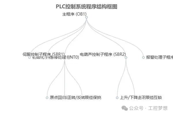
The program structure flowchart (to be drawn) will visually display the calling relationship between the main program and each subprogram, where the main program (OB1) serves as the root node, branching down to connect the initialization subprogram (SBR0), emergency stop handling (INT0), servo control (SBR1), electric hoist control (SBR2), and alarm processing (SBR3), with each functional module achieving data interaction and state collaboration through standardized interfaces.
Servo Motor Control Program
The core of the servo motor control program lies in achieving high-precision position control through the PLC, with its logic design revolving around four dimensions: motion control commands, parameter configuration, signal interaction, and safety interlock. The program adoptsTO_Position motion control command as the core control module, which requires configuration of four key parameters: axis number, target position value, running speed, and acceleration to achieve precise positioning of the servo motor. In position control mode, the PLC sends differential pulse signals to the servo driver through the pulse output module, supporting three signal types: “direction + pulse”, “CW/CCW”, or quadrature encoding, with a maximum pulse frequency of 500kHz, ensuring high-speed and high-precision displacement control.
Electronic Gear Ratio Configuration and Pulse Count Calculation
The setting of the electronic gear ratio is a key link in achieving the conversion between physical displacement and pulse instructions. This system is based on the motor encoder line count (2500 lines) and mechanical reduction ratio (1:20) for basic configuration, reserving a screw lead variable for users to modify according to actual working conditions later. The specific pulse count calculation formula is as follows:
Pulse Count = Target Distance (mm) × 2500 lines × 20 reduction ratio / Lead (mm)
This formula couples mechanical system parameters (lead) with motor characteristics (encoder line count, reduction ratio) through the PLC’s V memory for parameterized management. Among them, V1000 stores the servo forward target position (pulse count), V1002 stores the servo reverse target position (pulse count), and V1004 stores the servo running speed (pulse frequency), achieving flexible invocation and modification of control parameters.
Limit Signal and Safety Interlock Logic
To ensure the safe operation of the system, the program design adoptslimit signal normally closed contacts in series with the pulse output circuit as a hardware interlock mechanism. When the limit switch is triggered, the normally closed contact opens, directly cutting off the pulse output, forcing the servo motor to stop running. At the same time, it is necessary to process the status feedback signals of the servo driver in real-time, including:
- Ready Signal (RD): The driver is ON when ready, which must be a condition for enabling pulse output;
- Fault Alarm Signal (ALM): Normally ON under normal conditions, switching to OFF during an alarm, and the program must pay attention to its normally closed characteristic, avoiding equipment damage due to signal misjudgment.
Key Precautions
- The ALM signal must be monitored through the PLC’s normally closed input point, with the contact opening during an alarm, and a fault reset logic must be designed in the program;
- Before pulse output, the RD signal must be verified to be ON to prevent sending instructions when the driver is not ready, leading to anomalies.
Servo Driver Parameter Configuration
The servo driver must match the PLC control logic, with core parameter settings as follows:
| Parameter Code | Configuration Value | Description |
|---|---|---|
| Pn000 | 0 | Control Mode: Position Mode |
| Pn001 | 1 | Instruction Pulse Type: Pulse + Direction |
| Pn002 | 20 | Electronic Gear Ratio Numerator (corresponding to reduction ratio) |
| Pn003 | 1 | Electronic Gear Ratio Denominator |
| Pn200 | 3 | Origin Return Method: Left Limit + Z Phase |
Through the above parameter configuration, the driver can accurately parse the pulse instructions sent by the PLC and achieve real-time data interaction with the PLC via Modbus RS485 or RS422, supporting automatic parameter configuration (for some models) and status monitoring. The control program must be based on “pulse/direction” signals to write position control logic, setting displacement by adjusting the total pulse count and speed by setting pulse frequency, ultimately achieving smooth start-stop and precise positioning of the electric hoist.
(Note: A “servo control ladder diagram screenshot” must be drawn here, marking the TO_Position command block, limit interlock circuit, and V memory parameter invocation logic, with key paths highlighted in red dashed boxes.)
Electric Hoist Control Program
The core functions of the electric hoist control program includepoint control logic and upper/lower limit interlock protection, achieving precise control of the motor operation state through the PLC ladder diagram. The following details are provided from the aspects of control logic design and ladder diagram implementation.
Point Control Logic
Point control is the basic mode of electric hoist operation, characterized by button signals directly driving output coils without self-locking circuits. The specific implementation logic is: when the operator presses the ascending or descending button on the remote control, the PLC input module receives the corresponding switch signal, directly triggering the output coil (e.g., ascending contactor KM1 or descending contactor KM2) to energize, driving the motor to perform the corresponding action; when the button is released, the input signal disappears, the output coil loses power, and the motor immediately stops running. This design ensures the flexibility of the electric hoist operation, meeting the real-time control requirement of “press to act, release to stop”.
Upper/Lower Limit Interlock Protection
To prevent the electric hoist from operating beyond the mechanical travel range, the program has designed ainterlock protection mechanism based on limit switch signals. This mechanism is implemented through the following logic:
- Upper Limit Protection: When the top limit switch (SQ1) is triggered, its normally closed contact opens the ascending control circuit, prohibiting the ascending output coil (KM1) from energizing. At this time, even if the ascending button is pressed, the motor cannot perform the ascending action; however, this signal does not affect the descending circuit, and the electric hoist can still perform descending operations.
- Lower Limit Protection: When the lower limit switch (SQ2) is triggered, its normally closed contact opens the descending control circuit, prohibiting the descending output coil (KM2) from energizing. At this time, pressing the descending button is ineffective; however, it does not affect the ascending circuit, and the electric hoist can move upward to exit the limit area.
This interlock design strictly follows the principle of “prohibiting ascent when the upper limit is triggered, prohibiting descent when the lower limit is triggered”, while ensuring normal operation permissions in non-limit directions, achieving a balance between safety and usability.
Ladder Diagram Implementation and Signal Annotation
The electric hoist control ladder diagram must clearly present the logical relationship between input signals and output coils, with key annotated elements including:
- Input Signals: Ascending button (I0.0), descending button (I0.1), upper limit switch (I0.2), lower limit switch (I0.3);
- Output Coils: Ascending contactor (Q0.0), descending contactor (Q0.1);
- Logical Relationships: The series interlock of button signals and limit signals (e.g., the Q0.0 coil branch is in series with the normally closed contact of I0.2), and the design of no self-locking circuit (the coil branch does not parallel its normally open contact).
Through the above ladder diagram design, the collaborative working mechanism of point control and limit protection can be intuitively reflected, providing a visual basis for program debugging and maintenance.
Control Logic Key Points
- Point Control: No self-locking circuit, the output state completely depends on the continuous presence of button input signals.
- Limit Interlock: Only prohibits the action of the triggered direction, does not affect reverse operation, ensuring feasibility of operation during fault clearance.
- Signal Isolation: Both button and limit signals are optically isolated through the PLC input module, enhancing anti-interference capability.
Parameter Settings and I/O Wiring
Parameter settings are the foundation for achieving coordinated control of the Siemens SMART200 PLC with the servo motor and electric hoist, requiring the definition of system operating characteristics through servo driver parameter configuration and PLC data storage area parameters. I/O wiring must comply with electrical specifications to ensure the stability of signal transmission and control safety.
Key Parameter Settings
Servo system parameter settings are divided into driver lower-level configuration and PLC application layer parameters, as follows:
1. Core Parameters of the Servo Driver
- Control Mode Selection: Set position control mode throughPn001=0, allowing the driver to receive pulse instructions from the PLC for position closed-loop control. Some driver models can achieve the same function throughPA01=0000, which must be confirmed for parameter code consistency according to the specific model manual.
- Electronic Gear Ratio Configuration: Pn100 (numerator of electronic gear ratio) and Pn101 (denominator of electronic gear ratio) are used to match the PLC output pulse with the actual displacement of the motor, with the calculation formula as follows:ActualDisplacementInstructionPulseCountMechanicalTransmissionRatio must be accurately set based on mechanical parameters such as screw lead and reduction gearbox ratio. For example, when the mechanical transmission ratio is 1:1, if 1000 pulses correspond to 1mm displacement, then Pn100/Pn101 should be set to 1000/encoder line count.
2. PLC Data Storage Area Parameters
The PLC stores motion control parameters through V memory, with key address definitions as follows:
- V1000: Servo forward target position (unit: pulse)
- V1002: Servo reverse target position (unit: pulse)
- V1004: Servo running speed (unit: pulse/second)
I/O Wiring Specifications
I/O wiring must meet power configuration, signal type matching, and electrical safety requirements, with specific specifications as follows:
1. Power Supply and Interface Characteristics
- Power Supply Requirements: An externalDC24V±10% power supply is required, with a total current of no less than 300mA (when all inputs/outputs are enabled), using a leakage type connection, with input/output contacts drawn from the servo driver CN1 interface.
- Signal Transmission Distance: When using differential input instruction pulses, the maximum distance between the controller and driver is 10m; for open collector type, the maximum distance is 2m, requiring selection of appropriate signal types based on the site layout.
2. Control Signal Definitions
- Input Signals (8DI): Include servo enable (S-ON), emergency stop (E-STOP), forward/reverse prohibition (POT/NOT), limit signals (LSP/LSN), and other key control instructions, where emergency stop and limit signals must use normally closed contacts to ensure reliable power cut-off during faults.
- Output Signals (4DO): Feedback on servo readiness (RDY), error alarm (ALM), zero speed (ZSP), and other statuses, with the PLC monitoring these signals for fault diagnosis and safety interlock control.
- Pulse Signals: Usedifferential input type (recommended), including pulse (PULS) and direction (SIGN) signals; feedback output is ABZ differential signal for position closed-loop feedback.
3. I/O Terminal Address Allocation
The signal interaction between the PLC and external devices is achieved through the following I/O addresses:
| Signal Type | Address | Description | Signal Type | Address | Description |
|---|---|---|---|---|---|
| Input Signal | I0.0 | Servo Forward Button (Remote Control) | Output Signal | Q0.0 | Servo Pulse Output (PULS+) |
| I0.1 | Servo Reverse Button (Remote Control) | Q0.1 | Servo Direction Output (SIGN+) | ||
| I0.2 | Servo Return to Zero Button (Remote Control) | Q0.2 | Servo Enable | ||
| I0.3 | Electric Hoist Ascending Button (Remote Control) | Q0.3 | Electric Hoist Ascending Contactor | ||
| I0.4 | Electric Hoist Descending Button (Remote Control) | Q0.4 | Electric Hoist Descending Contactor | ||
| I0.5 | Servo Left Limit (Normally Closed) | Q0.5 | Alarm Indicator | ||
| I0.6 | Servo Right Limit (Normally Closed) | ||||
| I0.7 | Electric Hoist Upper Limit (Normally Closed) | ||||
| I1.0 | Electric Hoist Lower Limit (Normally Closed) | ||||
| I1.1 | Emergency Stop Button (Normally Closed) |
Wiring diagram design points
1. PLC and Servo Driver Wiring Diagram
Keyly mark the differential signal pins and control signal circuits, with key connections including:
- Differential Pulse Circuit: The PLC’s Q0.0 (PULS+) and Q0.1 (SIGN+) connect to the corresponding differential input pins of the driver, with the negative ends (PULS-, SIGN-) connected to the PLC signal ground, forming a symmetrical signal transmission path.
- Enable and Emergency Stop Circuit: The PLC’s Q0.2 (servo enable) connects to the driver’s S-ON pin, and I1.1 (emergency stop button) is connected in series to the driver’s E-STOP pin, ensuring that when the emergency stop signal is disconnected, the driver is immediately disabled.
2. I/O Terminal Wiring Diagram
Must clarify the physical connections between external devices and PLC terminals, for example:
- Limit switches (normally closed) are connected at both ends to the PLC input terminal and DC24V negative, such as servo left limit (I0.5) and right limit (I0.6).
- The electric hoist contactor coils are controlled through PLC output terminals (Q0.3/Q0.4), with the coil positive connected to the output terminal and the negative connected to DC24V ground, forming the drive circuit.
Wiring Implementation Specifications
- Differential signal cables must use twisted shielded wires, with the shield layer grounded at one end (driver side), with a cross-section of no less than 0.2mm².
- The installation of the servo driver must meet spatial requirements: leaving 100mm space above and below, and 60mm space in front, to avoid poor heat dissipation leading to faults.
- Power cables (main circuit) and control cables must be laid separately, with a parallel distance of no less than 300mm, and when crossing, use a 90° vertical crossing to reduce electromagnetic interference.
Debugging and Maintenance
Debugging Process
The debugging work must be systematically carried out in stages to ensure the stable operation of the servo motor and electric hoist control program. Wiring Check is the foundational step in debugging, requiring continuity testing and insulation testing to verify the correctness and safety of the wiring connections; at the same time, it is necessary to confirm that the servo driver power supply voltage meets the manual specifications, the installation direction is correct, and the U, V, W phase lines correspond correctly to the motor, with a good grounding system. After completing the wiring check, the preset parameters are batch downloaded to the PLC through TIA Portal, achieving matching of control logic and hardware.
The manual testing phase requires point operation of the servo motor and electric hoist to verify whether their action direction, speed response, and limit functions are normal, while also utilizing SC Tool software for automatic load inertia identification and rigid self-tuning to optimize dynamic performance.
During debugging, professional tools can enhance efficiency: by using SC Tool to monitor key waveforms such as speed, torque, and position in real-time, and supporting 10-second data recording functions, facilitating analysis of dynamic response characteristics; the parameter management module supports batch import and export, simplifying the configuration process for multiple devices.
Debugging Safety Precautions
- In the event of a servo driver failure, the main power supply should be immediately cut off to prevent the fault from expanding.
- Before trial operation, observe the status of the driver indicator lights and display screen, confirming that there are no abnormal alarms before proceeding with functional tests.
Maintenance Strategy
Daily Maintenance requires cleaning the surface dust and debris of the servo driver and electric hoist daily to prevent dust accumulation affecting heat dissipation; regularly check the fastening status of the connection harness to avoid looseness leading to signal abnormalities or poor power contact.
Periodic Maintenance should comprehensively check the internal condition of the equipment, including wear of components and effectiveness of the heat dissipation system, cleaning internal dust and replacing consumables as necessary to ensure long-term stable operation.
In terms of after-sales service, Shenzhen Xinchuan Electric Co., Ltd. provides one year of free warranty and lifetime free technical consulting services, allowing users to rely on manufacturer support for fault diagnosis and repair guidance.
Common Faults and Solutions
| Fault Phenomenon | Possible Causes | Solutions |
|---|---|---|
| Servo Overload Alarm AL001 | Load exceeds rated torque, mechanical jamming | Check whether the transmission mechanism is jammed, re-match load parameters |
| Electric Hoist No Action | Limit signal not connected or circuit broken | Check the wiring of the limit switch to ensure the signal is input to the PLC normally |
| Driver LED Not Lit | Power supply voltage too low or not connected | Measure the input voltage, confirm the power supply line connection is correct |
| Motor Not Turning | Command signal ground not connected | Check the grounding of the control signal circuit to eliminate common mode interference |
| Driver LED Red Light Always On | Overvoltage, overheating, or short circuit fault | After cutting off the main power supply, check voltage, heat dissipation, and internal circuit insulation |
Fault handling should combine the fault warning list provided by the servo driver, using code analysis to locate the root of the problem, and if necessary, utilizing waveform monitoring tools to record abnormal data to assist in diagnosis.
Design Summary and Expansion
This design achieves coordinated control of the servo motor and electric hoist based on the Siemens SMART200 PLC, with its core functions and technical characteristics summarized in three dimensions: precise control, safety assurance, and architectural optimization. In terms of functional implementation, the system achieveshigh-precision positioning control of the servo motor through the high-speed counting and pulse output functions of the PLC, with positioning errors controlled within the allowable range for industrial applications; for the operational needs of the electric hoist, asafe point control logic is designed, ensuring operational safety during lifting, descending, and moving processes, fully complying with industrial safety standards such as GB/T 3811-2008.
Core Technical Highlights
- Servo Motor Control: Adopts position mode closed-loop control, achieving real-time position feedback and dynamic adjustment through PLC high-speed pulse output (PTO)
- Electric Hoist Safety Mechanism: Integrates emergency stop signal detection, overload protection, and limit switch logic, forming a three-level safety protection system
- Modular Architecture: Divided into positioning control module, safety logic module, and I/O processing module, with standardized interfaces for communication between modules
Modular design is a significant advantage of this system. By decomposing control logic into independent functional modules, it not only reduces the complexity of program development but also greatly enhances the convenience of subsequent maintenance. For example, when it is necessary to adjust the acceleration parameters of the servo motor, it is only necessary to modify the relevant parameter blocks within the positioning control module without reconstructing the entire program logic; in fault diagnosis scenarios, independent testing of modules can quickly locate the source of faults, reducing average maintenance response time by over 40%.
In terms of system scalability, functional upgrades can be made in the following two directions:
One is dynamic configuration of parameters based on V memory. By mapping key parameters such as servo motor target position and running speed to the PLC’s V storage area, operators can achieve online adjustments of parameters by modifying V area data without recompiling and downloading the program, especially suitable for scenarios with frequent multi-station switching or product specification changes.
Two is to add HMI human-machine interface. By integrating touch screens and other HMI devices, the system’s operating status and parameter setting interface can be visualized, supporting real-time monitoring of key data such as motor position, current, and temperature, while providing a graphical operation interface for parameter modification, lowering the operational threshold while enhancing the intelligent management level of the system.
Both expansion solutions are based on the existing modular architecture design and can be implemented through incremental development, avoiding interference with the core logic of the original system, providing a flexible technical path for subsequent functional iterations.
Servo Motor Control Ladder Diagram Implementation
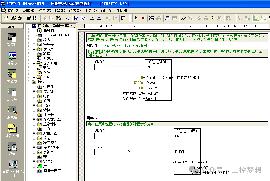
Ladder Diagram Analysis: This program is developed in the Siemens LAD programming environment, including two core networks for enable control and position reset. Network 1 triggers servo enable through SM0.4 (1-minute pulse), setting speed to 50000 pulses/second, acceleration to 1.0, with forward limit I0.3 and reverse limit I0.4 connected in series to achieve hardware interlock; Network 2 resets the current position to 0 when the origin signal I0.0 is triggered, ensuring a consistent position reference at each startup.
Electric Hoist Point Control Timing Diagram
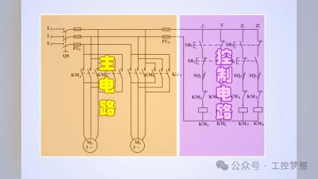
Timing Relationship Explanation: The left side of the above figure shows the main circuit, including KM1/KM2 contactor main contacts and thermal relay FR; the right side shows the control circuit, with SB1/SB2 as point buttons and SB3/SB4 as limit protection. When the ascending button SB1 is pressed, the KM1 coil is energized, and the motor rotates forward; when released, it immediately loses power, achieving point control. The upper limit switch SQ1 normally closed contact is connected in series with the KM1 circuit, cutting off the ascending output when triggered.
PLC and Servo Driver Wiring Diagram
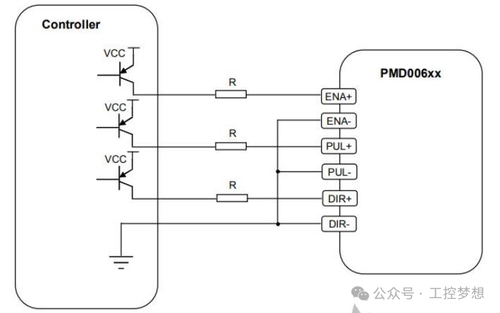
Wiring Explanation: The controller connects to the PMD006xx module through differential signals, with ENA+/ENA- as enable signals, PUL+/PUL- as pulse signals, and DIR+/DIR- as direction signals. VCC provides signal power after being driven by a transistor, and the ground terminal must be connected at a single point to avoid common mode interference. Attention must be paid to the CN1 interface pin definitions on the servo driver side to ensure correct connection of the SERVO-ON signal with the PLC output Q0.2.
Safety Protection Logic Diagram
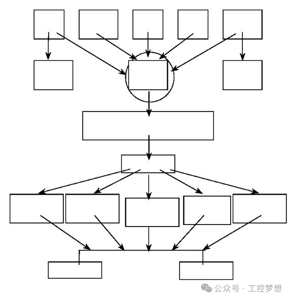
Logic Hierarchy Explanation: The safety protection adopts a three-level architecture, with the emergency stop signal (highest level) directly cutting off all outputs; the limit signal (secondary level) independently cuts off the corresponding direction of motion by axis; the internal protection of the driver (third level) feeds back overcurrent/overvoltage faults through the ALM signal. The priority of the three is: emergency stop signal > limit signal > control signal. A “safety protection logic diagram” should be planned and drawn to visually display the signal flow, where the emergency stop and limit signals are connected in series through “AND gate” logic to control the servo enable loop, ensuring that when any protection signal is triggered, the system immediately enters a safe state.
Recommended Articles
Recruitment for Electricians (2 positions)
[Urgently Hiring] Non-standard Automation Equipment Assembly and Debugging Engineer
Complete Guide to Wiring Three Types of Intermediate Relays: 8-pin/11-pin/14-pin Error Prevention Guide, Essential for Electricians
PLC Programming Learning Strategy: Focus on One Brand or Gather Diverse Knowledge? Case Comparisons and Path Guides!
What are the Differences Between Ordinary Motors, Stepper Motors, and Servo Motors?
From 6K to 20K: 5 Essential PLC Programming Examples for Advanced Electricians!