Siemens PLCs are widely used in the field of automation control due to their reliability and flexibility. For beginners, PLC programming may seem a bit complex, but once you grasp the basic programming concepts and methods, and gradually deepen your learning, you will find it is not difficult at all. Today, I will bring you a detailed guide to getting started with Siemens PLC programming, helping you quickly master the core points of programming!
1. Introduction to PLC Programming
What is PLC?
A PLC (Programmable Logic Controller) is a computer system specifically designed for industrial automation. It receives signals from external sensors and input devices, processes them through a program, and outputs signals to actuators, thereby achieving automated control.
The Siemens PLC system has high stability, reliability, and expandability, supports multiple programming languages, and can meet various automation control needs. For beginners, the Siemens S7 series (such as S7-1200, S7-1500) is the most commonly used model, equipped with rich functions and an easy-to-use programming environment.
Siemens PLC supports various programming languages, among which the most commonly used are Ladder Diagram (LD), Function Block Diagram (FBD), Structured Text (ST), and Instruction List (IL). For beginners, Ladder Diagram is the easiest to understand as it resembles a circuit diagram, making it easy to visualize.
2. Basic Knowledge of Siemens PLC Programming
Input/Output (I/O)
The inputs and outputs of a PLC are the basis of the control process. The input side receives signals from devices such as sensors, switches, and buttons, while the output side sends control signals to actuators such as relays and motors.
Digital Input: Such as switches, buttons, and other discrete inputs.
Digital Output: Such as relays, lights, and other discrete outputs.
Analog Input: Such as temperature sensors, pressure sensors, and other analog inputs.
Analog Output: Such as control valves and motor speed control.
In PLCs, relays can be simulated through Ladder Diagrams to control the logical relationships between inputs and outputs. Timers are used to implement delay functions, commonly used to control the start and stop time of devices.
Contacts: Simulate the input signals of switches. Typically used to check device status.
Coils: Simulate the control signals of output devices.
Timers: Used for timing control of device start and stop.
Counters: Used to record the number of occurrences of certain events.
Data Transfer Instructions (Move, Compare, etc.): Used for transferring, comparing, and storing data.
3. Basic Programming Structure and Ladder Diagram
Basic Concepts of Ladder Diagram Programming
Ladder Diagram is the most commonly used programming language for PLCs, named for its structure resembling a circuit diagram. It mainly consists of two elements:
Contacts: Represent input signals (such as switches, buttons, etc.).
Coils: Represent output signals (such as lights, relays, etc.).
Writing a Ladder Diagram typically follows a left-to-right, top-to-bottom order, making it concise and easy to understand. Each “rung” represents a logical operation.
Let’s look at a simple start-stop control example: starting a motor with a button and stopping it when the stop button is pressed.
Input: Start button (I0.0), Stop button (I0.1)
Output: Motor (Q0.0)
The Ladder Diagram code is as follows:
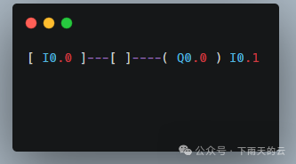
When the start button (I0.0) is pressed, the motor output signal (Q0.0) is “true”.
When the stop button (I0.1) is pressed, the motor output signal (Q0.0) is “false”, meaning the motor stops.
The basic operation of Ladder Diagrams is logical control, and it is essential to understand the relationship between contacts and coils for proper utilization.
During program debugging, it is often necessary to add and test “hypothetical” conditions to ensure system stability.
4. Programming Environment and Debugging
TIA Portal: Siemens PLC Programming Environment
Siemens’ TIA Portal (Totally Integrated Automation Portal) is an integrated environment for programming and debugging PLCs. It provides a graphical programming interface for easy hardware configuration, program writing, debugging, and monitoring.
Project Creation: In TIA Portal, you can start PLC programming by creating a new project. The project includes hardware configuration and program sections.
Hardware Configuration: Configure the PLC hardware in the project, selecting the appropriate CPU and I/O modules.
Programming: In the programming section, you can choose languages such as Ladder Diagram, Function Block Diagram, etc., for writing programs.
Download and Debugging: After completing the program, download it to the PLC through TIA Portal and use the monitoring function for real-time debugging.
Online Monitoring: Use the monitoring function to view the real-time status of the PLC; during debugging, you can directly view input and output signals to help quickly locate issues.
Breakpoints and Stepping: Set breakpoints to execute the program step by step, helping you accurately find where the problem lies.
5. Practical Application Cases
Case 1: Traffic Light Control
A common Siemens PLC programming project is a traffic light control system. We need to control the traffic lights to switch automatically based on time.
Input: Time settings for red, green, and yellow lights (e.g., I0.0: red light time, I0.1: green light time).
Output: Control signals for red, green, and yellow lights (e.g., Q0.0: red light, Q0.1: green light, Q0.2: yellow light).
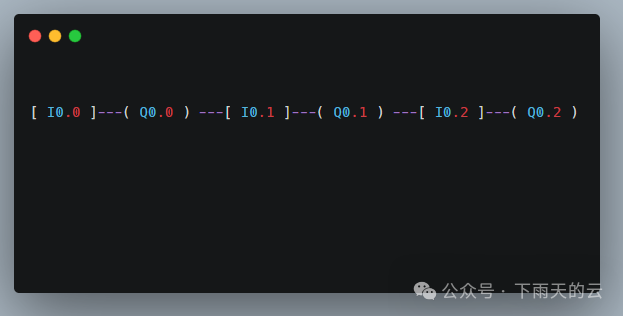
By setting appropriate timers, control the switching of the traffic lights. This project serves as a great introductory exercise, helping to understand the basic logic and timing control of PLCs.
6. Common Questions and Solutions
Question 1: How to debug timer issues?
When debugging timers, the most common issue is that the timer does not reach the preset delay. You can check the current value of the timer using the online monitoring function to ensure that the program logic is correct and that the timer settings are appropriate.
If the PLC’s input/output is unresponsive, first check whether the hardware wiring is correct and whether the I/O modules are functioning properly. Secondly, check the input/output instructions in the program through the programming software to confirm whether they are set correctly.
The key to learning Siemens PLC programming is to master the basic programming concepts, understand Ladder Diagram logic, and become familiar with debugging tools. Improving programming skills requires extensive practice; it is recommended to work on practical projects, starting with simple control tasks and gradually challenging more complex projects. Through continuous programming and debugging, you will find that PLC programming is actually full of fun.
Work on more cases: Practice through real projects to understand the input/output logic of PLCs.
Learn to debug: Use debugging tools for real-time monitoring and debugging of programs to quickly locate issues.
Reference manuals: Siemens’ official manuals and programming documents are excellent learning resources.
Gradually accumulate experience, and you will soon become a PLC programming expert!