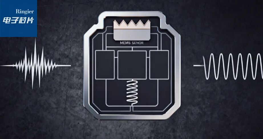
Image Source / Doubao
MEMS accelerometers are increasingly used in environments with frequent and severe mechanical stress. This article explores the key differences between impact resistance and vibration stability, two core metrics that determine the reliability of sensors under harsh conditions.
The article outlines relevant testing standards, failure mechanisms, and design strategies to enhance sensor robustness, using ADI accelerometers and sensors as examples to illustrate how mechanical margin and damping characteristics affect sensor performance in vibration environments, and introduces how impact testing assesses system-level damage resistance. Understanding the differences between these two important metrics is crucial for ensuring that the selected sensor meets both performance requirements and reliability standards.
Source / ADI
Author / Pablo del Corro, Application Engineer
Part 1
Introduction
MEMS-based accelerometers are increasingly applied in harsh environments; these environments not only involve mechanical stress but also sustained stress. Two core metrics are often noted in accelerometer datasheets: impact resistance and vibration stability.
Although the two may seem similar, their design purposes and testing methods are fundamentally different. Understanding the differences is key to selecting the appropriate sensor for specific application scenarios.
Part 2
Main Body
Impact Resistance: Responding to Sudden Stress
Impact resistance refers to the ability of an accelerometer to withstand non-repetitive, high-magnitude acceleration events. Such events typically occur during the handling and assembly of components (integrated circuits, ICs) or when equipment accidentally falls.
• Testing Standard: IEC 60068-2-27.
• Testing Method: Apply a specific magnitude and duration of half-sine wave pulse to all axes of the sensor.
• Testing Purpose: Ensure that the sensor maintains normal functionality after experiencing occasional but extreme impacts.
• Failure Mechanism: Typically leads to severe failures, such as the breaking of cantilever beams in MEMS structures, but may also cause system-level issues, such as internal wire bond failures or chip cracking.
Vibration Stability: Responding to Daily Stress
In contrast, vibration stability measures the ability of the sensor to maintain reliable operation in a continuous or repetitive vibration environment; such environments are common in many industrial and transportation applications.
• Testing Standard: Typically MIL-STD-883 Method 2007 (or standards defined by the manufacturer).
• Testing Method: Apply continuous random vibration within specified magnitude and frequency ranges.
• Testing Purpose: Verify the long-term reliability of the sensor in a vibrating environment during operation.
• Failure Mechanism: Often due to wear of protective structures, leading to sticking or particulate contamination issues.
Why Distinguish Between the Two
The stress effects of impact and vibration on sensors are fundamentally different. A sensor with an impact resistance of thousands of g may fail under sustained vibration of hundreds of g. This distinction is crucial for ensuring the sensor’s damage resistance and performance. Impact resistance addresses non-repetitive, high-magnitude impacts that could lead to system-level failures, while vibration stability focuses on long-term reliability.
1 “g” refers to gravitational acceleration (9.81m/s²).
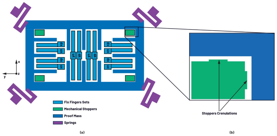
Figure 1. (a) Schematic diagram of MEMS accelerometer structure. (b) An enlarged view of one of the limiters. The limiter protects the MEMS structure during high-impact events.
The design of MEMS sensors plays a decisive role in their resistance to both impact and vibration metrics. For example, mechanical limiters and anti-sticking coating materials are part of the design measures used to protect the integrity of MEMS structures. Anti-sticking coatings can create low surface energy and/or electrical insulation, while mechanical limiters prevent the detection mass from fully contacting the fixed finger group.
Figure 1 shows a simplified structural schematic of a MEMS accelerometer. Mechanical limiters typically feature serrated protrusions that are 4µm to 5µm wide (small bumps), which can reduce contact area during high-impact events, thus helping to avoid sticking issues.
In heavy machinery such as bulldozers, accelerometers are used as tilt sensors to ensure normal operation on uneven terrain or to achieve terrain leveling. In such applications, accelerometers may endure peak magnitudes of sustained random vibration reaching tens of g (even exceeding 100g), and must possess high tilt accuracy, temperature stability, and repeatability.
From a performance perspective, accelerometers like the ADXL357B are ideal choices. Although its full-scale range is limited to ±40g, it can withstand greater vibrations. The vibration safety zone largely depends on the mechanical design of the sensor, including resonant frequency, damping characteristics, and the acceleration input required to trigger the mechanical limiters (known as mechanical margin). To illustrate the vibration safety zone, we can analyze the relationship between mechanical margin and frequency, as shown in Figure 2.
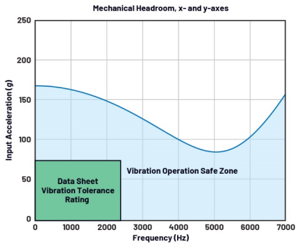
Figure 2. The relationship between mechanical margin and frequency of the ADXL357B. The mechanical margin decreases near the resonant point, highlighting the importance of damping in sensor design. According to the specifications of MIL-STD-883 Method 2007 test condition C, the rated specifications of the ADXL357B are: capable of withstanding continuous random vibration with a frequency range of 0Hz to 2kHz and a peak magnitude of 70g.
This helps engineers understand the size of the margin before the detection mass contacts the limiters, and understand the role of the sensor’s resonant frequency and quality factor in this process. When the input vibration is mechanically amplified by the quality factor, the closer the vibration frequency is to the sensor’s resonant frequency, the more effectively the mechanical margin is reduced.
Electrical Bandwidth and Mechanical Limits
The internal signal chain of an accelerometer typically includes analog and digital filters, and new sensors like the ADXL380 even feature digital equalization filters that can effectively extend bandwidth flatness to 4kHz. This feature is particularly useful in applications such as road noise cancellation (RNC); in such scenarios, accurately detecting wideband vibrations is essential to generate effective noise-resistant signals.
However, it is important to note that electrical filtering or equalization cannot eliminate the physical excitation experienced by the MEMS structure. The sensor will still endure mechanical stress, and if the operation exceeds the mechanical margin of the sensor, it may lead to sticking, fatigue, or structural degradation. Therefore, even if the electrical output exhibits linear characteristics within the extended bandwidth range, designers must ensure that the vibration magnitude remains within safe mechanical limits.
Impact and Sensor Full-Scale Range
It is noteworthy that the ADXL357B (±40g range) and ADXL380 (up to ±16g range) have the same damage resistance level as sensors like the ADXL373 (±400g range), all rated for a peak magnitude of 10,000g with a pulse width of 0.1ms for half-sine wave impact curves.
However, the vibration mechanical margin of the ADXL373 is much higher. The impact resistance level can be viewed as a system-level test: the test subject includes not only the MEMS sensor itself but also the integrity of internal wire bonds, chip mounting, packaging, and solder joints, all of which must undergo testing.
MEMS sensors from ADI may withstand over 10,000g of repeated impacts without structural failure, but the same may not be true for other components of the system that make up such devices.
Impact Testing
Due to the need for specialized equipment (such as drop towers or impact tables that can reach several meters and require precise control), reproducing standardized impact tests internally within companies is often quite challenging. Therefore, engineers often seek practical alternatives. One common method is to reduce the peak acceleration while extending the pulse width to maintain equivalent impact energy.
The principle of this method is that the area under the acceleration-time curve (i.e., velocity) is a key indicator of impact strength, as it is directly related to impact energy. For the intensity of half-sine impact pulses, the impact velocity can be estimated using Formula 1:

Where V is velocity (in m/s), A is peak acceleration (in m/s²), and D is pulse duration (in ms). For example, according to IEC 60068-2-27, an impact of 200g acceleration lasting 3ms is equivalent to an impact of 3000g acceleration lasting 0.2ms, both producing an impact velocity of approximately 3.8m/s. This equivalence makes it easier to obtain testing devices while still approximating the mechanical energy of standard impact events.
Part 3
Conclusion
Impact resistance and vibration stability are often misunderstood as interchangeable metrics, but in MEMS accelerometers, they represent fundamentally different stress characteristics and failure mechanisms. Impact events, though occasional, are of extremely high intensity and require robust mechanical design to avoid catastrophic damage; whereas vibration is continuous and latent, requiring sensors to possess long-term reliability and wear resistance.
Understanding the differences between the two is an important foundation for engineers selecting sensors for harsh environments. By considering factors such as mechanical margin, damping characteristics, and system-level robustness, designers can ensure that the selected sensor can withstand the rigors of harsh environments while ensuring long-term stable operation.
Ultimately, matching sensor specifications with the mechanical stress characteristics of the application scenario is key to achieving durability and accuracy. By selecting the appropriate sensor and clearly understanding the performance limitations and advantages of the sensor, engineers can confidently deploy MEMS technology in extreme environments.
*Disclaimer: This article is the original work of the author. The content reflects their personal views, and our reposting is solely for sharing and discussion purposes, not representing our endorsement or agreement. If there are any objections, please contact us.
For reprints or submissions, please contact | [email protected]
For more information on electronic chips, please follow
Click “Read the original text” to enjoy a free subscription to the “Ringier Electronic Chip” special electronic newsletter
 Like
Like  Recommend
Share Now