7.3.3 Flow Sensors
(1) Concept
A flow sensor is a device that measures the flow rate (instantaneous flow), cumulative flow, or both of fluids (including liquids, gases, steam, etc.). It converts the flow information of the fluid into usable output signals (such as current, voltage, digital signals, etc.) for the display, recording, and control of flow data in process automation.
Flow data is typically expressed in two ways:
1) Instantaneous flow: The volume or mass of fluid passing through the flow path per unit time, such as milliliters per minute (ml/min), cubic meters per hour (m³/h), grams per minute (g/min), kilograms per hour (kg/h), etc.
2) Cumulative flow: The total volume or mass of fluid that has passed through the flow path over a period of time, such as cubic meters (m³), milliliters (ml), liters (L), kilograms (kg).
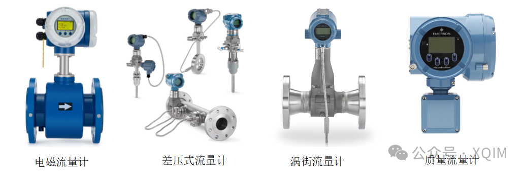
Figure 7-69 Flow Sensor
(2) Categories
Flow sensors can be classified based on their measurement principles into the following categories:
1) Mechanical (Volumetric)
Working principle: The mechanical measurement chamber fills and empties with fluid repeatedly, continuously counting the chamber volume.
Representative types: Oval gear flow meters, rotary (Roots) flow meters.
Characteristics: Extremely high accuracy, but has moving parts that are prone to wear and clogging.
2) Differential pressure type
Working principle: Based on Bernoulli’s equation, when fluid flows through a throttling element (such as an orifice plate) in a pipeline, a pressure difference is created before and after the element, which is proportional to the square of the flow rate.
Representative types: Orifice flow meters, Venturi tubes, V-cone flow meters.
Characteristics: Simple structure, long application history, but has significant permanent pressure loss and a narrow measurement range (range ratio).
3) Electromagnetic flow meters:
Working principle: Based on Faraday’s law of electromagnetic induction, conductive fluids cutting through magnetic field lines generate induced electromotive force.
Characteristics: No pressure loss, can measure corrosive and dirty media, but can only measure conductive liquids.
4) Vortex flow meters:
Working principle: A flow obstruction is placed in the fluid, creating alternating vortices (Karman vortex street) downstream, with the vortex frequency proportional to the flow rate.
Characteristics: No moving parts, robust and durable, can measure steam, gas, and liquid, but sensitive to vibrations.
5) Turbine flow meters:
Working principle: Fluid flow drives a turbine to rotate, with the turbine speed proportional to the flow rate.
Characteristics: High accuracy, fast response, but requires clean fluid to prevent bearing wear.
6) Ultrasonic flow meters:
Working principle: Measures the time difference or frequency difference of ultrasonic waves propagating in the downstream and upstream directions to calculate flow rate.
Characteristics: No pressure loss, can be installed externally (clamp-on type), suitable for large diameter pipelines.
7) Thermal mass flow meters:
Working principle: Calculates mass flow rate by measuring the amount of heat carried away by the fluid (temperature difference or power change).
Characteristics: Mainly suitable for gases, with minimal pressure loss.
8) Coriolis mass flow meters:
Working principle: Utilizes the Coriolis effect generated when fluid flows through a vibrating tube.
Characteristics: Can directly and accurately measure the mass flow of various fluids (liquids, gases) and can simultaneously measure density, but is expensive.
9) Float flow meters (rotor flow meters): Fluid pushes a float in a conical tube from bottom to top, with the float position indicating flow rate. Simple and intuitive structure, commonly used for small flow measurements.
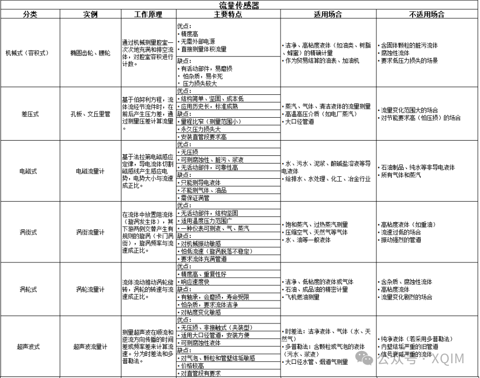
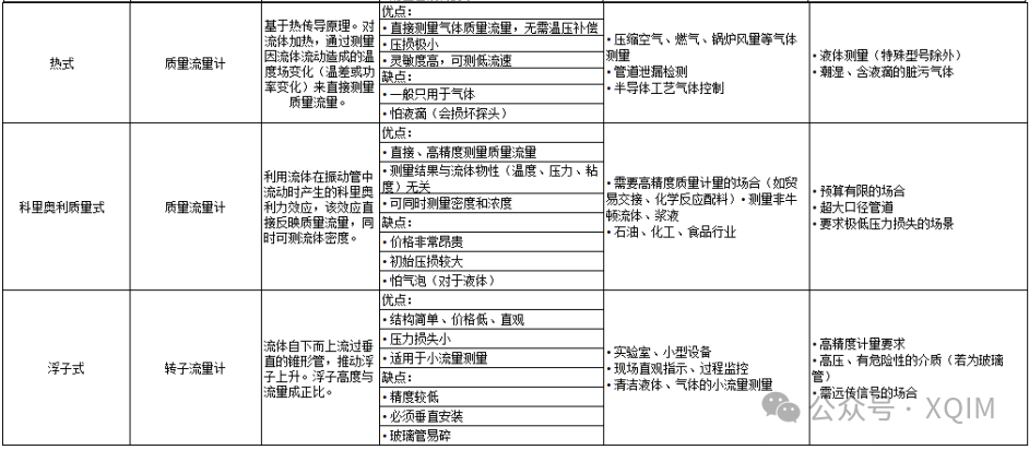
Figure 7-70 Classification and Characteristics of Flow Sensors
(3) Main Parameters
1) Measurement range (span): The minimum and maximum flow rates that the sensor can effectively measure, with a larger range ratio indicating better adaptability.
2) Accuracy: The degree of deviation between the measured value and the true value, usually expressed as a percentage of full scale (%FS).
3) Repeatability: The consistency of multiple measurements of the same flow under the same conditions.
4) Operating pressure and temperature: The fluid pressure and temperature environment in which the sensor can operate stably over the long term.
5) Output signal: Such as 4-20mA, pulse/frequency signals, RS485/MODBUS, HART, and other digital signals. The pulse/frequency signal can be converted into instantaneous flow.
6) Response time: The time required for the sensor output signal to reach 63.2% or 90% of the stable value after a change in flow.
7) Fluid characteristics: Viscosity, density, conductivity (for electromagnetic types), corrosiveness, etc.
8) Pipe diameter (DN): Matches the size of the field pipeline.
9) Pressure loss: The resistance caused by the sensor to fluid flow, with lower pressure loss being more energy-efficient.
10) Others: Power supply voltage, relevant certification, etc.
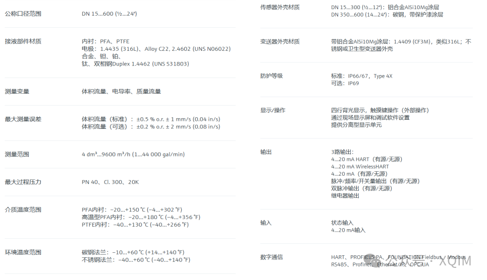
Figure 7-71 Specifications of E+H Proline Promag P300 Electromagnetic Flow Meter
(4) Selection
To ensure accurate selection of flow sensors, it is recommended to fill out the “Instrument Condition Form” or “Automatic Control Condition Form” to gather all information for comprehensive consideration; the following is the condition form for flow meter selection;
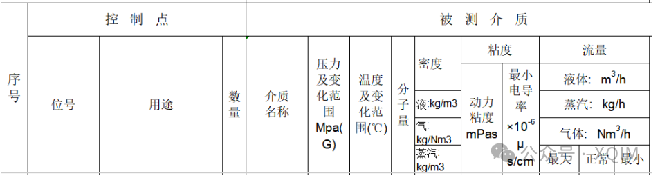
Figure 7-72 Control Points and Measured Media in the Flow Meter Selection Table
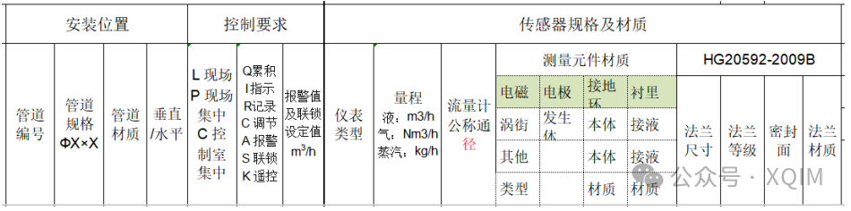
Figure 7-73 Installation Position, Control Requirements, Sensor Specifications, and Material Content in the Flow Meter Selection Table
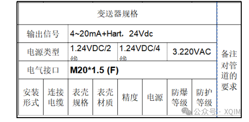
Figure 7-74 Specifications of the Transmitter in the Flow Meter Selection Table
Note: Since the selection of instruments and valves greatly affects the control results and data accuracy of the process control system, generally, larger enterprises have instrument engineers responsible for this; it is recommended that the selection of instrument valves be handled by experienced engineers and confirmed by suppliers.
(5) Precautions
1) For liquid measurements, it is essential to ensure that the sensor is always completely filled with fluid. Liquid media should avoid installation at the highest point of the pipeline, while gas media should avoid installation at the lowest point; the best position is in the rising section of the pipeline.
2) The flow meter should be installed in the direction indicated by the arrow on the housing, and must not be installed in reverse.
3) Some flow meters (mass flow meters) have strict requirements for installation orientation, and the installation instructions must be followed.
4) Flow meters (such as vortex, electromagnetic, turbine, differential pressure types) require sufficient straight pipe sections upstream and downstream to ensure stable fluid velocity distribution without vortices. Generally, upstream 10D and downstream 5D or more is required. If there are disturbance sources such as valves, elbows, or pumps, even longer straight pipe sections are needed. It is strictly prohibited to install flow meters directly behind the outlet of a pump, next to a valve, or near a tee (D is the pipe diameter).
5) The flow meter flange should be concentric with the pipeline flange, and forced alignment is strictly prohibited to avoid additional stress. Gaskets should not protrude into the pipeline to prevent interference with fluid flow and false signals.
6) Instruments sensitive to vibrations, such as vortex flow meters, should be kept away from vibration sources (such as large pumps, compressors) or take vibration reduction measures.
7) Avoid installation in areas with excessively high temperatures or direct sunlight, as the electronic components have working temperature limits. For flow meters installed outdoors, proper insulation and heating measures must be taken to prevent freezing and cracking.
8) In flammable and explosive environments, instruments that meet the explosion-proof rating must be selected and installed according to explosion-proof regulations.
9) When first introducing gas or liquid, be sure to slowly open and close the valve to avoid sudden fluid impacts that could damage the internal structure of the sensor (such as the turbine blades, vortex shedding body, etc.).
10) For liquid pipelines, after starting, air trapped in the pipeline should be vented to prevent “water hammer” phenomena and inaccurate measurements. For gas pipelines, liquid accumulation at low points should be vented.
11) Regularly clean or replace the filter at the front end of the flow meter to prevent clogging. Regularly check if the electrodes of the electromagnetic flow meter are covered with dirt, and if the lining shows signs of wear, bubbling, or other abnormalities. Before maintenance operations, the pipeline must be shut off, and the medium inside the pipeline must be drained, depressurized, and cooled. For pipelines transporting toxic, harmful, corrosive, high-temperature, and high-pressure media, strict safety regulations must be followed, and protective gear must be worn.
12) Flow meters will drift over time with use. They should be calibrated regularly according to process requirements or relevant standards.
———————————————————————–