In 1979, Schneider Electric established a bus protocol for industrial sites called the Modbus protocol. Nowadays, many industrial applications using RS485 communication adopt the Modbus protocol. Today, we will explore RS485 communication and the Modbus communication protocol.
1. Introduction
In fields such as industrial control, power communication, and smart instruments, serial communication is typically used for data exchange. Initially, the RS232 interface was used, but due to the complex industrial environment, various electrical devices generate considerable electromagnetic interference, which can lead to signal transmission errors.
In 1979, Schneider Electric established a bus protocol for industrial sites called the Modbus protocol. Nowadays, many industrial applications using RS485 communication adopt the Modbus protocol. Today, we will explore RS485 communication and the Modbus communication protocol.
2. RS485 Communication
1. In fact, RS232 was already established before RS485, but RS232 has several shortcomings:
1) The signal voltage level of the interface is relatively high, reaching several volts, which can easily damage the circuit chips, and it is not compatible with TTL levels. Therefore, when connecting to microcontroller circuits, a conversion circuit must be added.
2) The signal lines used for the interface form a common ground mode with other devices, which can easily introduce interference and has poor anti-interference performance.
3) The transmission distance and speed are limited, with a maximum communication distance of only a few dozen meters; it can only communicate between two points and cannot achieve multi-machine networking.
2. To address the above shortcomings of the RS232 interface, new interface standards such as RS485 emerged, which has the following characteristics:
1) Logic “1” is represented by a voltage difference of + (2—6)V between the two wires; logic “0” is represented by a voltage difference of – (2—6)V. The signal voltage level of the interface is lower than that of RS232, making it less likely to damage the circuit chips, and this level is compatible with TTL levels, allowing for easy connection to TTL circuits.
2) RS485 communication is fast, with a maximum data transmission rate exceeding 10Mbps; its internal physical structure uses a balanced driver and differential receiver combination, significantly enhancing its anti-interference capability.
3) The maximum transmission distance can reach approximately 1200 meters, but transmission speed and distance are inversely proportional. To achieve the maximum communication distance, the transmission speed must be below 100KB/s; if longer distances are needed, repeaters can be used.
4) Multiple devices can be connected on the bus for multi-machine communication, with various RS485 chips supporting 32, 64, 128, 256, or more devices.
3. RS485 can be configured in two-wire and four-wire systems, but four-wire systems can only achieve point-to-point communication and are rarely used. The two-wire configuration is a bus topology, allowing for a maximum of 32 nodes on the same bus. In RS485 communication networks, a master-slave communication method is typically used, with one master and multiple slaves.
4. In many cases, when connecting the RS-485 communication link, a simple twisted pair is used to connect the “A” and “B” terminals of each interface, neglecting the connection of signal ground. This method may work in many situations but poses significant risks for two reasons:
1) Common-mode interference problem: The RS-485 interface uses a differential signal transmission method and does not require detection relative to a reference point; the system only needs to detect the potential difference between the two wires. However, people often overlook that the transceiver has a certain common-mode voltage range, which is -7 to +12V for RS-485 transceivers. The entire network can only operate normally if the common-mode voltage in the network lines is within this range. When the common-mode voltage exceeds this range, it can affect the stability and reliability of communication, even damaging the interface.
2) EMI issue: The common-mode part of the signal output from the driver requires a return path. Without a low-resistance return path (signal ground), it will return to the source in the form of radiation, causing the entire bus to act like a large antenna radiating electromagnetic waves.
5. Since PCs typically only come with RS232 interfaces, the following methods can be used to obtain the RS485 circuit on a PC:
1) Use an RS232/RS485 conversion circuit to convert the PC’s RS232 signal to RS485. It is best to choose surge-protected products with isolation for complex industrial environments.
2) Use a PCI multi-serial card that directly outputs RS485-type signals.
3. Modbus Communication Protocol
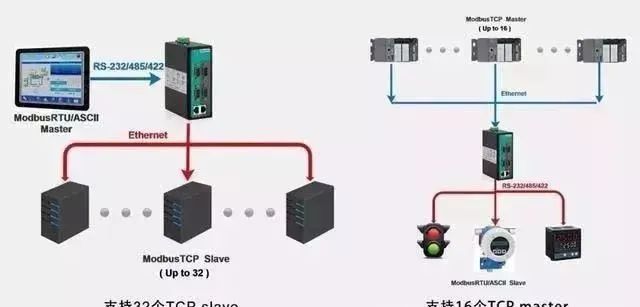
The Modbus protocol is a universal language used in electronic controllers. Through this protocol, controllers can communicate with each other and with devices over a network (such as Ethernet). It has become a general industrial standard. With it, control devices from different manufacturers can be connected into an industrial network for centralized monitoring.
This protocol defines a message structure that controllers can recognize, describes the process by which a controller requests access to other devices, how to respond to requests from other devices, and how to detect and log errors. It establishes a common format for the message domain structure and content.
1. Features of Modbus:
1) Standard and open, users can use the Modbus protocol freely and without charge, and it does not infringe on intellectual property rights. Currently, more than 400 manufacturers support Modbus, with over 600 products supporting it.
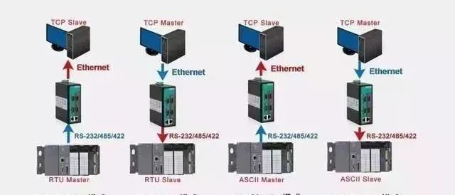
2) Modbus supports various electrical interfaces, such as RS-232 and RS-485, and can transmit over various media, including twisted pairs, fiber optics, and wireless.
3) The frame format of Modbus is simple, compact, and easy to understand. It is user-friendly and easy for manufacturers to develop.
2. Explanation of Modbus Register Types:
1) Coil Status: Output ports that can set the output status of ports and can also read the output status of that bit;
2) Discrete Input Status: Input ports that can change the input status through external settings; readable but not writable;
3) Holding Registers: Certain parameters set during controller operation; readable and writable;
4) Input Registers: Certain parameters obtained from external devices during controller operation; readable but not writable.
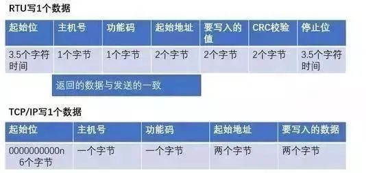
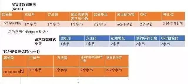
3. Modbus Communication Data Format:
1) Single Write:
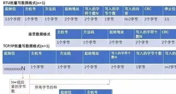
2) Multiple Writes:
3) Read:
4. Brief Description of Modbus Function Codes:
Function codes can be divided into bit operations and byte operations, where the smallest unit for bit operations is Bit, and for byte operations, it is 2 bytes (Byte).
(1) Bit operation instructions: Read Coil Status 01H, Read Discrete Input Status 02H, Write Single Coil 05H, Write Multiple Coils 0FH.
(2) Byte operation instructions: Read Holding Registers 03H, Read Input Registers 04H, Write Single Holding Register 06H, Write Multiple Holding Registers 10H.
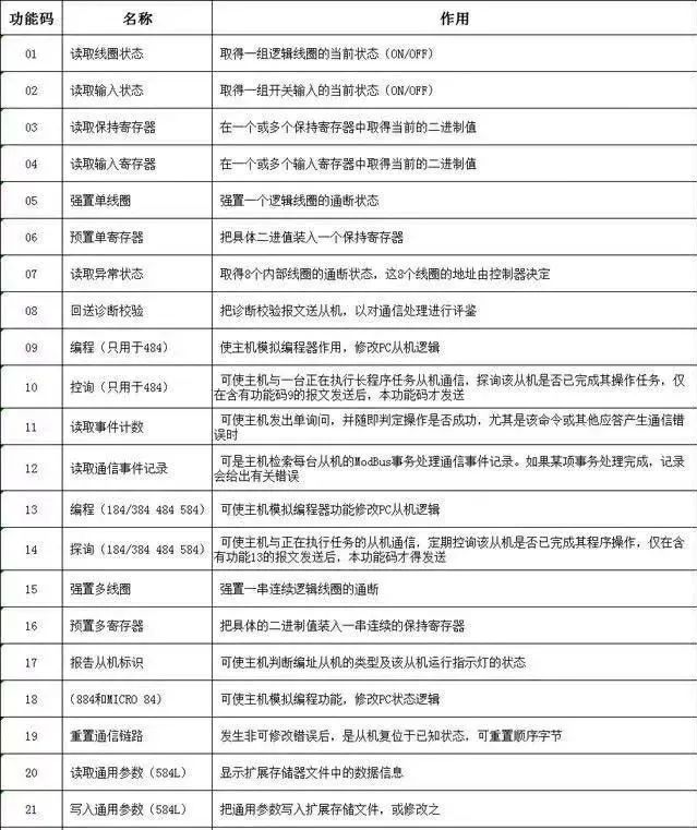
5. Modbus Function Codes:

Complete Question Bank for the 2021 Electrical Engineer Entry Exam (with Answers)
Having trouble troubleshooting inverter faults? Just one click is all it takes!
Want to brush through all electrical exam questions with just one click? Have you got this magic tool yet?
Which of the five major electrical drawing software (CAD, Eplan, CADe_simu…) do you pick?
The latest electrical version of CAD drawing software, with a super detailed installation tutorial!
The latest electrical drawing software EPLAN, with a super detailed installation tutorial!
Common issues for beginners using S7-200 SMART programming software (with download links)
Comprehensive electrical calculation EXCEL spreadsheets, generated automatically! No need to ask for electrical calculations!
Bluetooth headphones, electrical/PLC introductory books are available for you to claim? Come and get your electrical gifts!
Basic skills in PLC programming: Ladder diagrams and control circuits (with 1164 practical cases of Mitsubishi PLC)
Still can’t understand electrical diagrams? Get the basics of electrical diagram reading and simulation software, and quickly get started with theory and practice!
12 free electrical video courses, 10GB of software/eBook resources, and 30 days of free electrical live classes are being offered!