

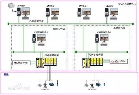
The ModBus network is an industrial communication system formed by connecting programmable controllers with intelligent terminals and computers through public or local dedicated lines. Its system structure includes both hardware and software. It can be applied to various data acquisition and process monitoring.
The ModBus network has only one master, and all communication is initiated by it. The network can support up to 247 remote slave controllers, but the actual number of slaves supported depends on the communication equipment used. With this system, each PC can exchange information with the central master without affecting its own control tasks.
Understanding the Modbus communication protocol allows for communication testing using various third-party software on-site.
The Modbus protocol includes ASCII, RTU, TCP, etc., and does not specify the physical layer. This protocol defines the message structure that controllers can recognize and use, regardless of the network over which they communicate. Standard Modicon controllers use RS232C for serial Modbus communication. The ASCII and RTU protocols of Modbus define the message and data structure, commands, and response methods. Data communication adopts a Master/Slave method, where the Master sends data request messages, and the Slave can send data back to the Master in response after receiving the correct message; the Master can also directly send messages to modify the Slave’s data, achieving two-way read and write.
The Modbus protocol requires data verification. In serial protocols, besides parity checks, the ASCII mode uses LRC checks, and the RTU mode uses 16-bit CRC checks. However, the TCP mode does not have additional verification requirements since TCP is a connection-oriented reliable protocol. Furthermore, Modbus uses a master-slave method to periodically send and receive data. In practical use, if a Slave site disconnects (e.g., due to failure or shutdown), the Master can diagnose it, and when the fault is repaired, the network can reconnect automatically. Therefore, the reliability of the Modbus protocol is relatively good.
For Modbus’s ASCII, RTU, and TCP protocols, TCP and RTU protocols are very similar; we just need to remove the two-byte checksum from the RTU protocol, then prepend five zeros and a six to the RTU protocol and send it through the TCP/IP network protocol.
Communication transmission is divided into an independent information header and the encoded data sent. The following definitions of communication transmission methods are also compatible with the ModBus RTU communication protocol:
Initial Structure = ≥4 bytes of time
Address Code = 1 byte
Function Code = 1 byte
Data Area = N bytes
Error Check = 16-bit CRC code
End Structure = ≥4 bytes of time
Address Code:The address code is the first byte of the communication transmission. This byte indicates which slave, set by the user, will receive the information sent by the master. Each slave has a unique address code, and responses will start with their respective address codes. The address code sent by the master indicates the address of the slave to which it will send, while the address code sent by the slave indicates the address of the slave responding.
Function Code:The second byte of the communication transmission. The ModBus communication protocol defines function numbers from 1 to 127. This instrument only utilizes a portion of these function codes. As a master requesting to send, the function code tells the slave what action to perform. As a slave responding, the function code sent by the slave is the same as the function code sent by the master and indicates that the slave has responded to the master’s operation. If the highest bit of the function code sent by the slave is 1 (e.g., function code greater than 127), it indicates that the slave did not respond to the operation or an error occurred in sending.
Data Area:The data area varies according to different function codes. The data area can be actual values, set points, or addresses sent from the master to the slave or from the slave to the master.
CRC Code:A two-byte error detection code.
When the communication command is sent to the instrument, the device with the corresponding address code receives the communication command, removes the address code, reads the information, and if there are no errors, executes the corresponding task; then it sends the execution result back to the sender. The returned information includes the address code, the function code of the executed action, the result data of the executed action, and the error check code. If there is an error, no information is sent.
1. Information Frame Structure
Address Code Function Code Data Area Error Check Code
8 bits 8 bits N × 8 bits 16 bits
The address code is the first byte (8 bits) of the information frame, ranging from 0 to 255. This byte indicates which slave, set by the user, will receive the information sent by the master. Each slave must have a unique address code, and only the slave that matches the address code can respond. When the slave sends back information, the corresponding address code indicates where the information comes from.
The function code sent by the master tells the slave what task to perform. The function codes listed in Table 1-1 have specific meanings and operations.
The data area contains what actions need to be performed by the slave or the information returned by the slave. This information can be values, reference addresses, etc. For example, if the function code tells the slave to read the value of a register, the data area must contain the starting address of the register to be read and the reading length. The address and data information will differ for different slaves.
The error check code can be used by the master or slave to determine whether the received information is erroneous. Sometimes, due to electronic noise or other interferences, information may undergo slight changes during transmission, and the error check code ensures that erroneous information during transmission does not take effect on the master or slave. This increases the safety and efficiency of the system. The error check uses the CRC-16 check method.
Note: The format of the information frame is basically the same: address code, function code, data area, and error check code.
2. Error Check
The Redundant Cyclic Code (CRC) consists of 2 bytes, that is, 16 bits of binary. The CRC code is calculated by the sending device and placed at the end of the sent information. The receiving device then recalculates the CRC code of the received information, comparing whether the calculated CRC code matches the received one. If they do not match, it indicates an error.
|
Function Code |
Name |
Function |
|
1 |
Read Coil Status |
Obtain the current state of a group of logical coils (ON/OFF) |
|
2 |
Read Input Status |
Obtain the current state of a group of switch inputs (ON/OFF) |
|
3 |
Read Holding Registers |
Obtain the current binary value in one or more holding registers |
|
4 |
Read Input Registers |
Obtain the current binary value in one or more input registers |
|
5 |
Force Single Coil |
Force the ON/OFF state of a logical coil |
|
6 |
Preset Single Register |
Load a specific binary value into a holding register |
|
7 |
Read Exception Status |
Obtain the ON/OFF status of 8 internal coils, whose addresses are determined by the controller |
|
8 |
Diagnostics Echo |
Send a diagnostic echo message to the slave to evaluate the communication processing |
|
9 |
Programming (only for 484) |
Allows the master to simulate the programmer’s function to modify the logic of the PC slave |
|
10 |
Inquiry (only for 484) |
Allows the master to communicate with a slave executing a long program task to inquire whether the slave has completed its operation, only after sending a message with function code 9 can this function code be sent |
|
11 |
Read Event Counter |
Allows the master to issue a single inquiry and then determine whether the operation was successful, especially when a communication error occurs with this command or other responses |
|
12 |
Read Communication Event Log |
Allows the master to retrieve the ModBus transaction processing communication event log of each slave. If a transaction processing is completed, the log will provide information about errors |
|
13 |
Programming (184/384 484 584) |
Allows the master to simulate the programmer’s function to modify the logic of the PC slave |
|
14 |
Inquiry (184/384 484 584) |
Allows the master to communicate with a slave executing a task, periodically inquiring whether the slave has completed its program operation, only after sending a message with function 13 can this function code be sent |
|
15 |
Force Multiple Coils |
Force the ON/OFF state of a series of consecutive logical coils |
|
16 |
Preset Multiple Registers |
Load specific binary values into a series of consecutive holding registers |
|
17 |
Report Slave Identification |
Allows the master to determine the type of addressed slave and the state of its operation indicator |
|
18 |
(884 and MICRO 84) |
Allows the master to simulate programming functions to modify the logic state of the PC |
|
19 |
Reset Communication Link |
After a non-modifiable error occurs, it resets the slave to a known state, allowing it to reset the sequence byte |
|
20 |
Read General Parameters (584L) |
Display data information in the extended memory file |
|
21 |
Write General Parameters (584L) |
Write or modify general parameters in the extended storage file |
|
22~64 |
Reserved for extended functions |
|
|
65~72 |
Reserved for user functions |
Reserved for user function extension codes |
|
73~119 |
Illegal Function |
|
|
120~127 |
Reserved |
Reserved for internal use |
|
128~255 |
Reserved |
For abnormal responses |
Among these function codes, the most commonly used are function codes 1, 2, 3, 4, 5, and 6, which can be used to perform read and write operations on digital and analog quantities of the lower machine.
1. Command 01, Read Readable and Writable Digital Registers (Coil Status):
The computer sends the command: [Device Address] [Command Number 01] [High 8 bits of Starting Register Address] [Low 8 bits] [High 8 bits of Registers to Read] [Low 8 bits] [Low 8 bits of CRC Check] [High 8 bits of CRC Check]

Example: [11][01][00][13][00][25][CRC Low][CRC High]
Meaning as follows:
<1>Device Address: Multiple devices can be connected on a 485 bus; the device address here indicates which device to communicate with. In this example, it is device number 17 (decimal 17 is hexadecimal 11).
<2>Command Number 01: The command number for reading digital quantities is fixed at 01.
<3>Starting Address High 8 bits, Low 8 bits: Indicates the starting address of the switch quantity to be read (starting address is 0). For example, the starting address in this example is 19.
<4>Register Count High 8 bits, Low 8 bits: Indicates how many switch quantities to read starting from the starting address. In the example, there are 37 switch quantities.
<5>CRC Check: The check is from the beginning up to this point.
Device Response: [Device Address] [Command Number 01] [Number of Returned Bytes] [Data1] [Data2] … [DataN] [High 8 bits of CRC Check] [Low 8 bits of CRC Check]

Example: [11][01][05][CD][6B][B2][0E][1B] [CRC High] [CRC Low]
Meaning as follows:
<1>Device Address and Command Number are the same as above.
<2>Returned Byte Count: Indicates the number of data bytes, which is the value of n in Data1, Data2 … n.
<3>Data1 … n: Since each data is an 8-bit number, each data represents the value of 8 switch quantities; each bit of 0 indicates that the corresponding switch is off, while 1 indicates it is on. For example, in the example, it indicates that device number 20 (index number 19) is on, device number 21 is off, device number 22 is on, device number 23 is on, device number 24 is off, device number 25 is off, device number 26 is on, device number 27 is on… If the queried switch quantities are not a multiple of 8, the high part of the last byte is meaningless and is set to 0.
<4>CRC Check is the same as above.
2. Command 05, Write Digital Quantity (Coil Status):
The computer sends the command: [Device Address] [Command Number 05] [High 8 bits of Register Address to Set] [Low 8 bits] [High 8 bits of Data to Set] [Low 8 bits] [Low 8 bits of CRC Check] [High 8 bits of CRC Check]

Example: [11][05][00][AC][FF][00][CRC High][CRC Low]
Meaning as follows:
<1>Device Address is the same as above.
<2>Command Number: The command number for writing digital quantities is fixed at 05.
<3>Register Address to Set High 8 bits, Low 8 bits: Indicates the address of the switch to be set.
<4>Data to Set High 8 bits, Low 8 bits: Indicates the state of the switch to be set. In the example, it indicates closing the switch. Note that only [FF][00] indicates closing, and [00][00] indicates opening; other values are illegal.
<5>Note that this command can only set the state of one switch.
Device Response: If successful, the computer returns the command as it was sent; otherwise, there is no response.
3. Command 03, Read Readable and Writable Analog Registers (Holding Registers):
The computer sends the command: [Device Address] [Command Number 03] [High 8 bits of Starting Register Address] [Low 8 bits] [High 8 bits of Registers to Read] [Low 8 bits] [High 8 bits of CRC Check] [Low 8 bits of CRC Check]

Example: [11][03][00][6B][00][03] [CRC High][CRC Low]
Meaning as follows:
<1>Device Address is the same as above.
<2>Command Number: The command number for reading analog quantities is fixed at 03.
<3>Starting Address High 8 bits, Low 8 bits: Indicates the starting address of the analog quantity to be read (starting address is 0). For example, the starting address in this example is 107.
<4>Register Count High 8 bits, Low 8 bits: Indicates how many analog quantities to read starting from the starting address. In the example, there are 3 analog quantities. Note that in the returned information, one analog quantity requires two bytes to return.
Device Response: [Device Address] [Command Number 03] [Number of Returned Bytes] [Data1] [Data2] … [DataN] [High 8 bits of CRC Check] [Low 8 bits of CRC Check]

Example: [11][03][06][02][2B][00][00][00][64] [CRC High] [CRC Low]
Meaning as follows:
<1>Device Address and Command Number are the same as above.
<2>Returned Byte Count: Indicates the number of data bytes, which is the value of n in Data1, Data2 … n. In this example, 3 analog quantities are returned, requiring a total of 6 bytes since each analog quantity requires 2 bytes.
<3>Data1 … n: Where [Data1][Data2] are the high and low 8 bits of the 1st analog quantity, and [Data3][Data4] are the high and low 8 bits of the 2nd analog quantity, and so on. The values returned in this example are 555, 0, and 100.
<4>CRC Check is the same as above.
4. Command 06, Write Single Analog Quantity Register (Holding Register):
The computer sends the command: [Device Address] [Command Number 06] [High 8 bits of Register Address to Set] [Low 8 bits] [High 8 bits of Data to Set] [Low 8 bits] [High 8 bits of CRC Check] [Low 8 bits of CRC Check]

Example: [11][06][00][01][00][03] [CRC High] [CRC Low]
Meaning as follows:
<1>Device Address is the same as above.
<2>Command Number: The command number for writing analog quantities is fixed at 06.
<3>Register Address to Set High 8 bits, Low 8 bits: Indicates the address of the analog quantity register to be set.
<4>Data to Set High 8 bits, Low 8 bits: Indicates the data for the analog quantity to be set. For example, in this case, the value of register 1 is set to 3.
<5>Note that this command can only set the state of one analog quantity.
Device Response: If successful, the computer returns the command as it was sent; otherwise, there is no response.
5. Command 16, Write Multiple Analog Quantity Registers (Holding Registers):
The computer sends the command: [Device Address] [Command Number 16] [High 8 bits of Register Address to Set] [Low 8 bits] [High 8 bits of Data Quantity] [Low 8 bits] [Data High 8 bits] [Low 8 bits] [……] [……] [High 8 bits of CRC Check] [Low 8 bits of CRC Check]
Example: [11][16][00][01][00][01][00][05] [CRC High] [CRC Low]
Meaning as follows:
<1>Device Address is the same as above.
<2>Command Number: The command number for writing analog quantities is fixed at 16.
<3>Register Address to Set High 8 bits, Low 8 bits: Indicates the address of the analog quantity register to be set.
<4>Data Quantity High 8 bits, Low 8 bits: Indicates the quantity of data to be set; here it is 1.
<5>Data High 8 bits, Low 8 bits: Indicates the data for the analog quantity to be set. For example, in this case, the value of register 1 is set to 5.
Device Response: If successful, the computer returns the command as it was sent; otherwise, there is no response.
Device Response: [Device Address] [Command Number 16] [High 8 bits of Register Address to Set] [Low 8 bits] [High 8 bits of Data Quantity] [Low 8 bits] [High 8 bits of CRC Check] [Low 8 bits of CRC Check], as in the above example returns:
[11][16][00][01][00][01] [CRC High] [CRC Low]
Highlights Review
1.Unveiling the Mysteries of License Plate and Barcode Recognition
2.Free: Halcon Programming Source Code (with Comments)
3.[Knowledge Sharing] How to Perform Halcon Calibration
4.[Limited Time Offer] ABB Robot Training Videos + PPT Materials + Learning Resources
5.[Limited Time Offer] 20 Types of Industrial Robots, 100+ Application Case Videos
6.[Knowledge Sharing] KUKA Robot Videos + PPT + Resources
7.[Free] Yaskawa and Nachi Robot Teaching Videos, Learning Resources
[Free] FANUC Robot Learning Videos + Resources
[Free] Mitsubishi and Omron Learning Resources
Welfare: Free Learning Resources for Mitsubishi FX5U
Is debugging industrial robots difficult?
Commonly Used Algorithms in Artificial Intelligence Technology Learning
S7-1200 Wireless Serial Communication with Other PLC/Configuration Software (Free Port)
There has never been a job called: High Pay, Low Workload, Close to Home, High Position, Light Responsibility!
15.Detailed Explanation of FANUC Robot Palletizing Programming

Source: Comprehensive Network, if there is infringement, please contact for deletion.


 Original Link