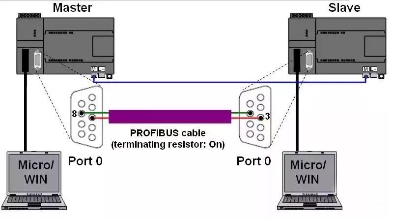
1. Hardware Setup The Modbus communication in the program is conducted between the 0 communication ports of two S7-200 CPUs (it is best for each CPU to have two communication ports). On the master side, communication can also be established using the corresponding library files “MBUS_CTRL_P1” and “MBUS_MSG_P1” through the 1st communication port. Communication port 1 connects with PG or PC via Micro/WIN, and the communication port 0 of the two CPUs is connected through a Profibus cable (the cable pin connections are 3, 3, 8, 8 -> see Figure 01). Additionally, it is necessary to ensure that they are logically connected.
2. Parameter Matching
For MODBUS communication, the master side requires the program libraries “MBUS_CTRL” and “MBUS_MSG”, while the slave side requires the program libraries “MBUS_INIT” and “MBUS_SLAVE”. In Micro/WIN, you need to create a new project for both the master and slave, with program and parameter settings as shown in Figure 02. It must be ensured that the “Baud” and “Parity” settings are consistent between the master and slave, and the “Slave” address in the program block “MBUS_MSG” must match the “Addr” set in the program block “MBUS_INIT” (see Figure 02). The baud rate of communication port 0 set in the “System Block” of Micro/WIN is unrelated to the MODBUS protocol (“Mode” = “1”).
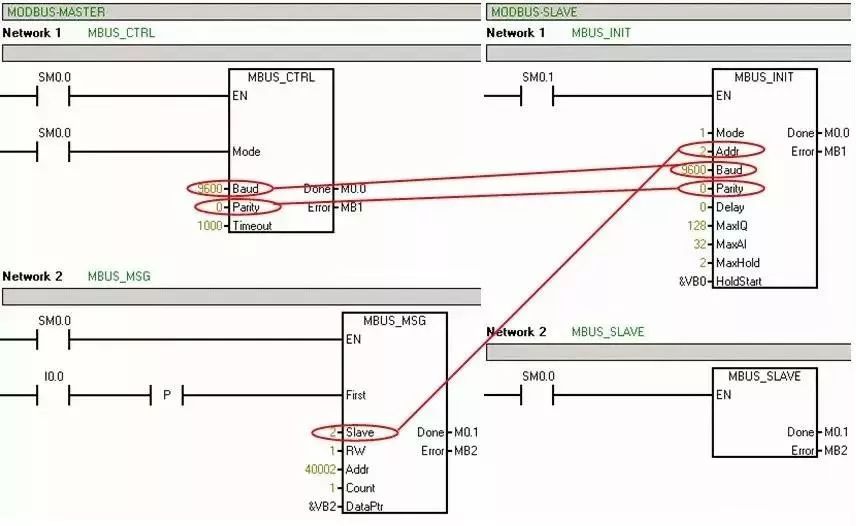
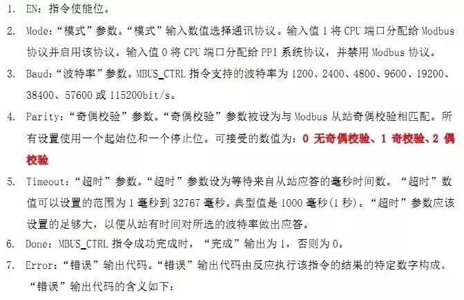
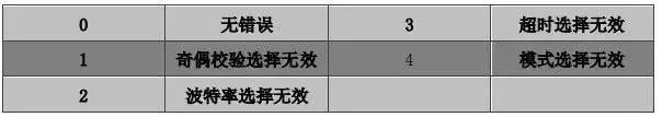
The table below lists the various parameter options of the program blocks and their meanings. Master MBUS_CTRL
MBUS_MSG


Slave MBUS_INIT
MBUS_SLAVE

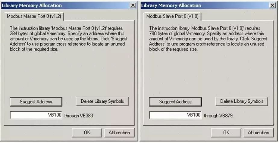
3. Library Storage Address After the project is completed, the library storage addresses must be defined in Micro/WIN. Once the storage area is defined, it must be ensured that it cannot be used by other programs under any circumstances (Master side: “DataPtr” + “Count” Slave side: “HoldStart” + “MaxHold”).
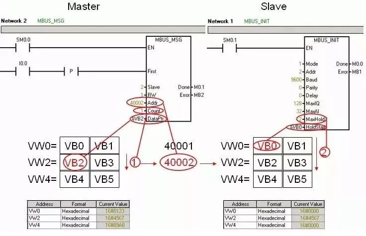
4. Transmission of Holding Register Values After downloading the program to the corresponding CPU, you can assign values to the V storage area on the master side in the status table, and then monitor the changes in values on the slave side. When the I0.0 of the master is enabled, the contents of VW2 are sent to the slave and written into the VW2 of the slave. The transmission of holding register values is shown in Figure 04. The pointer “DataPtr” represents the starting address of the V area being read. The parameter “Count” specifies the number of words to be written to the address “Addr” = “4xxxx” (holding register). The corresponding variables in the V storage area will be written to the starting address of the holding register “Addr” = “40002” (“RW” = “1”). The holding registers are transmitted in words, corresponding to the V area address of the slave. The pointer “HoldStart” specifies the initial address of the V storage area corresponding to the starting address of the holding register 40001. The target pointer of the slave’s V area can be calculated using the following formula: 2 * (Addr – 40001) + HoldStart = 2 * (40002 – 40001) + &VB0 = &VB2. Additionally, it must be ensured that the data area to be written by the master side is contained within the data area defined by “MaxHold”: MaxHold >= Addr – 40001 + Count = 40002 – 40001 + 1 = 2
End
In the comments section, everyone can supplement any inaccuracies or deficiencies in the article, so that the next person who sees it can learn more. What you know is exactly what everyone needs…
5000 Electrical CAD Engineering Drawings, Finally Organized, Scan the QR Code Below to Get Them for Free, Recommended to Save!


Previous Recommendations
How to View PLC Wiring Diagrams and Wire PLCs According to the Drawings?
How to Implement PID Automatic/Manual Adjustment Switching on Siemens S7-200 SMART PLC
How to Distinguish NPN from PNP? How to Wire with PLC?
Latest Electrical Drawing Software EPLAN, with Detailed Installation Tutorial!
After Watching His PLC Skills, I Finally Understand Why His Monthly Salary is 20,000!
Analysis of ABB Robot Handling Project Programs, So Detailed, You Will Understand After Watching!