In industrial control, power communication, and smart instrumentation, data exchange often relies on serial communication. Initially, the RS232 interface was the mainstream choice; however, due to the complexity of industrial sites, various electrical devices generate electromagnetic interference that can lead to signal transmission errors.
In 1979, Schneider Electric designed and launched a bus protocol specifically for industrial fields, known as the Modbus protocol. Now, many industrial applications using RS485 communication tend to use the Modbus protocol. In the industrial sector, the Modbus protocol is widely used when it comes to RS485 communication. Next, we will provide a detailed introduction to RS485 communication and the Modbus communication protocol.
1. RS485 Communication
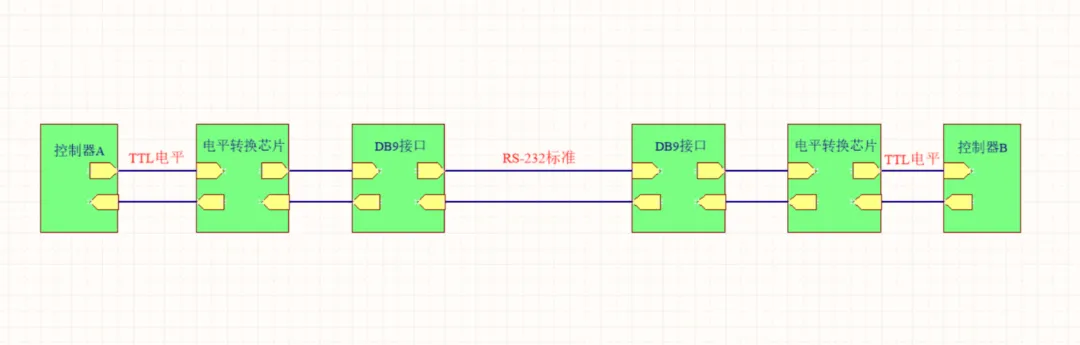
1. Prior to RS485, RS232 had already been introduced, but RS232 has some limitations:
1) Its interface signal voltage levels are relatively high, which may damage the interface circuit’s chip, and it is not compatible with TTL levels, requiring additional conversion circuits to connect with microcontroller circuits.
2) The common ground mode communication method of RS232 is prone to interference and has weak anti-interference performance.
3) Its transmission distance and speed are limited, with a maximum reach of only tens of meters, and it only supports communication between two points, making multi-machine networking impossible.
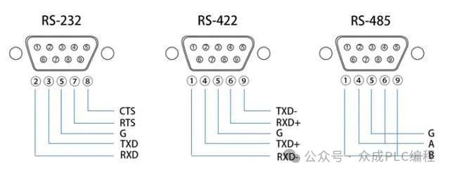
2. To overcome the limitations of RS232, new interface standards like RS485 emerged. RS485 has the following characteristics:
1) Logic “1” is represented by a voltage difference of + (2—6) V between the two wires, while logic “0” is represented by – (2—6) V. Its interface signal levels are lower than those of RS232, making it less likely to damage circuit chips, and it is compatible with TTL levels, facilitating connections with TTL circuits.
2) RS485 communication is fast, with a maximum data transmission rate exceeding 10 Mbps. It utilizes a combination of balanced drivers and differential receivers internally, significantly enhancing anti-interference capability.
3) Its maximum transmission distance can reach about 1200 meters, but the transmission speed is inversely proportional to the transmission distance. To achieve the maximum communication distance, a transmission speed below 100KB/s is required. If longer distances are needed, repeaters can be used.
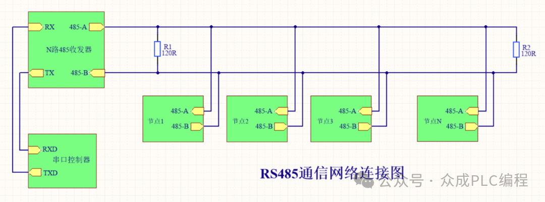
4) RS485 supports multi-machine communication, allowing multiple transceivers to be connected to the bus. Depending on the existing RS485 chips, the number of devices that can be connected varies, such as 32, 64, 128, 256, etc.
3. RS485 is divided into two-wire and four-wire systems. The four-wire system only supports point-to-point communication and is now rarely used. The two-wire system follows a bus topology, with a maximum of 32 nodes connected on the same bus. In RS485 communication networks, a master-slave communication method is typically used, where one master controls multiple slaves.
4. When connecting RS-485 communication links, sometimes the “A” and “B” terminals of each interface are simply connected with twisted pairs, neglecting the connection of the signal ground. This connection method may work in certain situations, but it has its risks. There are two reasons:
1) Common mode interference issues: RS-485 interfaces use differential transmission, eliminating the need for a reference point to detect signals. However, transceivers have a certain common mode voltage range (-7 to +12V). When the common mode voltage in the network lines exceeds this range, it will affect communication stability and may even damage the interface.
2) EMI issues: The common mode part of the signal output by the sending driver requires a low-resistance return path. Without this path (signal ground), the signal will return to the source in a radiated form, causing the bus to emit electromagnetic waves.
5. Since PCs are typically only equipped with RS232 interfaces, the following methods can be used to implement an RS485 circuit on a PC:
1) Use an RS232/RS485 conversion circuit to convert the RS232 signal from the PC’s serial port to RS485 signals. For complex industrial environments, it is recommended to choose products with surge protection and isolation features.
2) Use a PCI multi-serial port card, selecting an expansion card that outputs signals in RS485 type.
2. Modbus Communication Protocol
Modbus function codes are a set of instruction codes used in the Modbus communication protocol to indicate what operations devices should perform. They allow the master device (usually a computer or PLC) to communicate with slave devices (such as sensors, actuators, etc.) to read or write data.
Function codes can be broadly divided into bit operations and byte operations. The smallest unit for bit operations is a Bit, typically used to control single-bit operations such as switch states. The smallest unit for byte operations is 2 bytes (Byte), commonly used to read or write multi-byte data, such as register values.
Here are some common Modbus function codes and their descriptions:
Bit operation instructions:
01H: Read Coil Status
02H: Read Discrete Inputs Status
05H: Write Single Coil
0FH: Write Multiple Coils
Byte operation instructions:
03H: Read Holding Registers
Used to read one or more holding register values from slave devices. Holding registers are typically used to store device parameters or status information.
04H: Read Input Registers
Used to read one or more input register values from slave devices. Input registers are typically used to store data read from external devices (such as sensors).
06H: Write Single Holding Register
Used to write a value to a single holding register of a slave device.
10H: Write Multiple Holding Registers
Used to write values to multiple consecutive holding registers of a slave device. This is typically used to set device parameters or statuses. Note that the above function codes are represented in hexadecimal and have an “H” suffix. In actual communication, these function codes will be converted to binary format for transmission.

Additionally, there are other function codes for diagnostics or specific applications. The specific usage and meanings of these function codes may vary by device manufacturer, so it is necessary to refer to the device’s documentation or manual in practical applications.