 This article provides an in-depth study of the
 Modbus RTU protocol.
Background
Before introducing Modbus RTU, we can understand that Modbus was invented by Schneider Electric in 1979 and is the first truly industrial bus protocol used in the field. More than forty years later, it is still widely used in various industrial control fields. In addition to its stability, the reasons include:
-
Free; -
Easy to deploy and maintain; -
For vendors, there are not many restrictions on modifying local bits or bytes;
Modbus is an application layer messaging protocol on the seventh layer of the OSI model, which defines the hierarchy of open systems, the relationships between layers, and the possible tasks included in each layer, serving as a framework to coordinate and organize the services provided by each layer.
The OSI reference model does not provide a method of implementation, but describes some concepts for coordinating the development of communication standards between processes. In other words, the OSI reference model is not a standard but a conceptual framework used in the formulation of standards.
Modbus can be described in the OSI model as shown in the figure below;
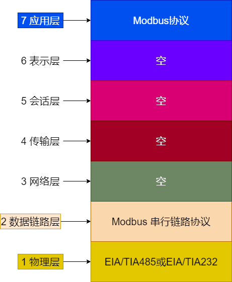
EIA485/TIA485refers toRS485. With the continuous development of technology, the 485 standard is currently maintained by the Telecommunications Industry Association (TIA), hence the name TIA-485. However, it is still acceptable for engineers and application guides to refer to it as RS-485;
Next, let’s introduce some serial link protocols.
Modbus Serial Link Protocol
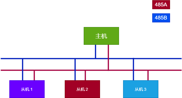
The Modbus serial link protocol is a master-slave mode (master and slave), half-duplex data transmission protocol. The 485 standard usually requires two wires, and at any given moment, there is one master and one slave communicating.
-
Master-slave mode: Typically, there is one master and multiple slaves on the bus, each slave has a unique ID, and the master addresses the slave through the ID for data transmission; -
Half-duplex transmission: In contrast to half-duplex is full-duplex, where full-duplex allows sending data and receiving data to occur simultaneously. Therefore, half-duplex is easy to understand, as it can only either send or receive data at the same time;
The overall structure diagram is as follows;
Here we also need to clarify a few points:
-
The slave cannot actively send data to the slave; it can only send data back to the master after the master sends data to the slave (sending a request), and then the slave receives the data sent by the master;
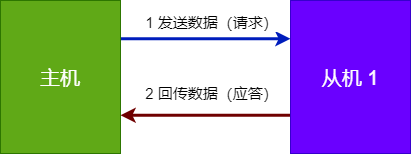
As mentioned earlier, Modbus is a half-duplex transmission, meaning when the master sends data, it cannot receive data. Therefore, there are two steps involved.
-
The master has two ways to send data: one is 1-to-1, and the other is 1-to-many, which is commonly referred to as broadcasting, where all slaves can receive the data sent by the master;
1-to-1 only requires sending data to a specific address of the slave, while broadcasting only requires setting the sending address to 0, so the broadcast address is 0;
Here we have roughly understood the data transmission situation between the master and slave, and next we will introduce the specific format of data transmission;
Transmission Modes
First, let’s talk about the two transmission modes in Modbus: RTU transmission mode and ASCII transmission mode;
-
RTU Transmission:
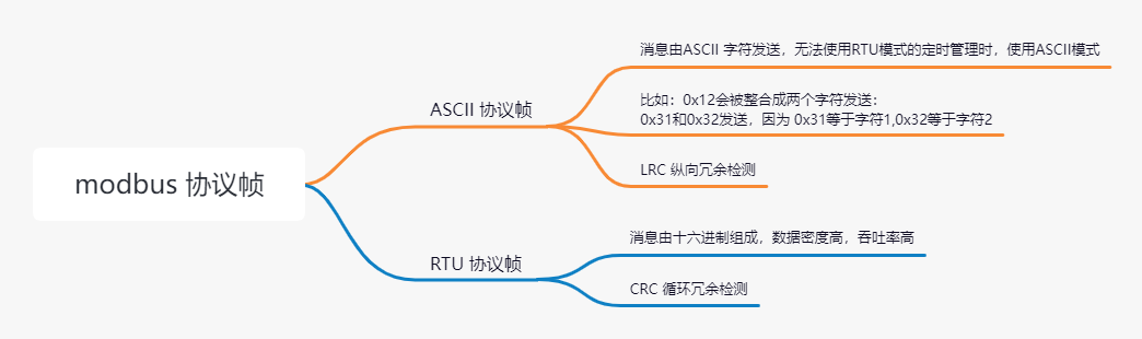
Remote Terminal Unitmode consists of messages composed of hexadecimal in Modbus, which has high data density and high throughput; -
ASCII Transmission: Messages are sent using ASCII characters, which are less efficient than RTU mode and are used when RTU mode’s timing management cannot be utilized;
For example,
0x12will be integrated into two characters for transmission:0x31and0x32,because
0x31equals character 1;0x32equals character 2
Next, we will mainly introduce Modbus RTU.
Frame Format
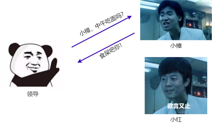
Before discussing the frame format, let’s imagine a conversation between people, where the most basic unit is a Chinese character, and they communicate using sentences composed of these characters, such as the dialogue below;
-
The boss asks: What are we eating for lunch? -
Little Zhang replies: Let’s eat!

Thus, communication between machines is similar; we can consider bytes as the most basic data unit, and sentences composed of bytes are communication frames;
However, now the situation changes, and besides Little Zhang, there is also Little Hong. To clarify who is speaking to whom, we need to add names at the beginning of the conversation:
-
Boss: Little Zhang, are we having noodles for lunch? -
Little Zhang: Boss, let’s go eat. -
Little Hong, who was not called, is just an observer;
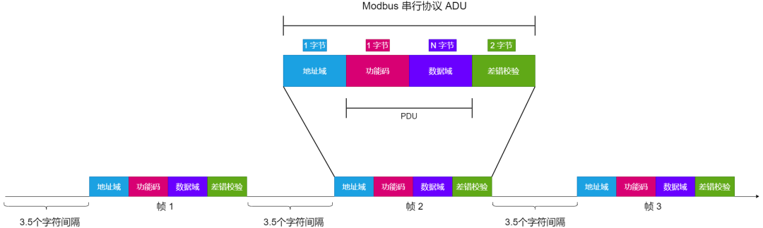
So let’s return to the data frame format of Modbus. The protocol defines a simple protocol data unit (PDU) for a basic communication layer, as shown in the figure below;
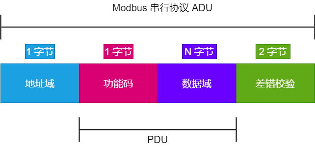
Thus, it is fundamentally divided into four parts: Address Field, Function Code, Data, and Error Check (CRC/LRC), collectively referred to as ADU (Application Data Unit). The data being transmitted must meet this format to be considered a complete frame. Comparing to the previous dialogue with the boss, we can simply understand it as follows:
-
Address Field: Can be understood as who to talk to; -
Function Code: Can be understood as specific actions, such as go do, come take, go eat, etc.; -
Data: Can be understood as specific content, such as noodles, rice, etc., or other items based on context; -
Error Check: Can be understood as ensuring that what is said is understandable; otherwise, others won’t comprehend it. In the protocol, CRC or LRC is typically used to ensure the transmitted data is error-free;
Next, let’s analyze the details further;
PDU
Modbus PDU (protocol data unit) format is defined as a function code followed by a set of associated data.
The size and content of the data are defined by the function code, and the entire PDU (function code and data) cannot exceed 253 bytes.
Each function code has a specific behavior that the device can flexibly implement based on the required application behavior.
The PDU specification defines the core concepts of data access and operation; however, the device may handle data in ways not explicitly defined in the specification.
Address Field
The address field occupies one byte, so generally, the addressing range is 0~255, typically using 1~147 in the system, with other addresses temporarily reserved. Additionally, each address on the same bus must be unique for the slaves.
Where 0 is the broadcast address;
Here is an initialization code for a slave in Freemodbus, where 0x02 is the address of this slave,
eMBInit(MB_RTU, 0x02, 3, 115200, MB_PAR_NONE);
Function Code
The function code takes one byte, so the range is 0~255. The protocol specifies that function codes are divided into three categories: common function codes, user-defined function codes, and reserved function codes. Overall, they are as follows;
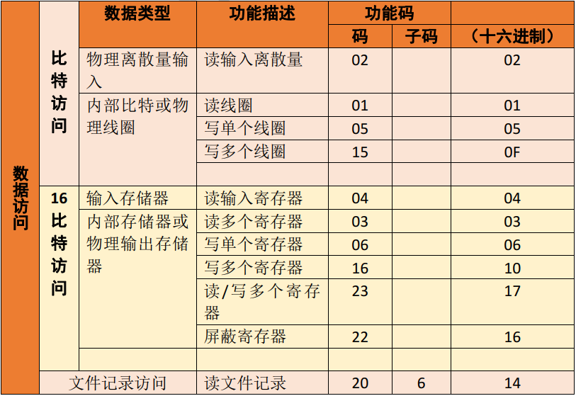
Common function codes must ensure their uniqueness, as defined by the Modbus organization, which has consistency testing for function codes, ensuring the reusability of the protocol to some extent.
From the table, we can see that common function codes are divided into four types:
-
Discrete Input: Read-only type, unit: bit; -
Coil: Read-write type, unit: bit; -
Input Register: Read-only type, unit: bytes; -
Holding Register: Read-write type, unit: bytes;
Here is the callback function for handling these four common function codes on the slave when porting the Freemodbus protocol:
//Input Register

eMBErrorCode eMBRegInputCB( UCHAR * pucRegBuffer, USHORT usAddress, USHORT usNRegs )
{
  eMBErrorCode    eStatus = MB_ENOERR;
  return eStatus;
}

//Holding Register
eMBErrorCode
eMBRegHoldingCB( UCHAR * pucRegBuffer, USHORT usAddress, USHORT usNRegs,
                 eMBRegisterMode eMode )
{
    eMBErrorCode    eStatus = MB_ENOERR;
    return eStatus;
}

//Coil Count
eMBErrorCode
eMBRegCoilsCB( UCHAR * pucRegBuffer, USHORT usAddress, USHORT usNCoils,
               eMBRegisterMode eMode )
{
    eMBErrorCode    eStatus = MB_ENOERR;
    return eStatus;
}

//Discrete Input Count
eMBErrorCode
eMBRegDiscreteCB( UCHAR * pucRegBuffer, USHORT usAddress, USHORT usNDiscrete )
{
    eMBErrorCode    eStatus = MB_ENOERR;
    return eStatus;
}
How Data is Transmitted at the Lower Level
First, let’s look at how the lowest level of Modbus data is sent. Yes, seeing RS485 and RS232, we naturally think of serial ports.
Thus, the fundamental data format can refer to the definition of serial port data, which includes start bits, data bits, parity bits, and stop bits; specifically as follows;
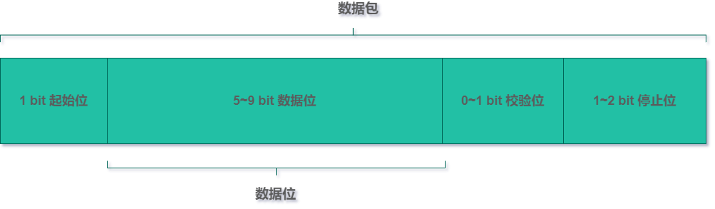
Therefore, we can define that:
Start Bit + Data Bit + Parity Bit (optional) + Stop Bit equals one character; thus, we can calculate the time required for a single character based on the baud rate of the serial port.
Next, let’s see how the Modbus frame is sent.
In RTU mode, the interval between frames must be at least 3.5 character times to indicate the start and end of the frame. Therefore, if you want to create a Modbus RTU yourself, you will need a timer to calculate the length of the idle time.
The entire data must be sent as a continuous stream of characters. If the length between two characters equals 1.5 character times, it is considered that the frame message is incomplete, and the device should not receive that message, as shown below;
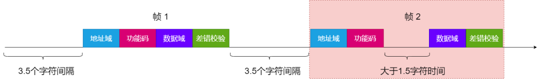
It is important to note that RTU requires the participation of timer interrupts. Therefore, the detection of 1.5 character time and 3.5 character time requires high-frequency interrupts when the serial communication speed is high, which increases system overhead.
Thus, typically when the baud rate is below 19200, one can strictly adhere to the 1.5 and 3.5 character time regulations.
If the baud rate exceeds 19200, it is necessary to meet two fixed times:
-
1.5 character time: 750 us; -
3.5 character time: 1.75 ms;
Conclusion
This article briefly introduces the Modbus RTU protocol, including serial link communication, frame format, and message format at the hardware link layer. Due to limited capabilities, there may be errors and omissions in this article. Please feel free to provide feedback.