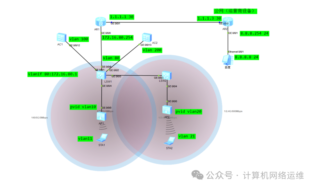
Today, it’s not just about Layer 3 networking; it also includes roaming between ACs. What does this mean? It means that two APs connected to different ACs can still achieve wireless roaming! The topology is quite simple, so let’s start configuring directly! Here is the online topology diagram!
🎏 SW1 Port Configuration!
[SW1]vlan batch 10 11 20 21 100 200
[SW1-GigabitEthernet0/0/1]port link-type trunk
[SW1-GigabitEthernet0/0/1]port trunk allow-pass vlan 100  to AC1
[SW1-GigabitEthernet0/0/2]port link-type trunk
[SW1-GigabitEthernet0/0/2]port trunk allow-pass vlan 200  to AC2
[SW1-GigabitEthernet0/0/3]port link-type trunk
[SW1-GigabitEthernet0/0/3]port trunk allow-pass vlan 20 to 21 to (SW2) AP2
[SW1]interface GigabitEthernet 0/0/4
[SW1-GigabitEthernet0/0/4]port link-type trunk
[SW1-GigabitEthernet0/0/4]port trunk pvid vlan 10
[SW1-GigabitEthernet0/0/4]port trunk allow-pass vlan 10 to 11 to AP1
🎏 SW2 Port Configuration!
[SW2-GigabitEthernet0/0/3]port link-type trunk
[SW2-GigabitEthernet0/0/3]port trunk allow-pass vlan 20 to 21
[SW2-GigabitEthernet0/0/4]port link-type trunk
[SW2-GigabitEthernet0/0/4]port trunk pvid vlan 20
[SW2-GigabitEthernet0/0/4]port trunk allow-pass vlan 20 to 21 to AP2
🎏 AC1 Port Configuration!
[AC1]vlan batch 100
[AC1]int GigabitEthernet 0/0/12
[AC1-GigabitEthernet0/0/12]port link-type trunk
[AC1-GigabitEthernet0/0/12]port trunk allow-pass vlan 100
AC1 uses vlanif100 as the original interface for CAPWAP, just ensure the interface passes vlan 100!
🎏 AC2 Port Configuration!
[AC2]vlan batch 200
[AC2-GigabitEthernet0/0/13]port link-type trunk
[AC2-GigabitEthernet0/0/13]port trunk allow-pass vlan 200
AC2 uses vlanif200 as the original interface for CAPWAP, just ensure the interface passes vlan 200!
🎏 SW1 Vlanif Interface IP Address Configuration and Description!
[SW1]interface vlanif10
[SW1-Vlanif10]description ap1     Port description: management VLAN gateway for ap1
[SW1-Vlanif10]ip address 172.16.10.252 24
[SW1]interface vlan 11
[SW1-Vlanif11]description ap1-sta           Description for terminal service (STA) VLAN gateway under ap1
[SW1-Vlanif11]ip address 172.16.11.252 24
[SW1]interface Vlanif 20
[SW1-Vlanif20]description ap2               Port description: management VLAN gateway for ap2
[SW1-Vlanif20]ip address 172.16.20.252 24
[SW1]int vlan 21
[SW1-Vlanif21]description ap2-sta           Description for terminal service (STA) VLAN gateway under ap2
[SW1-Vlanif21]ip address 172.16.21.252 24
[SW1]int vlan 100
[SW1-Vlanif100]description to-AC1           Description for communication with AC1 at Layer 3
[SW1-Vlanif100]ip address 172.16.100.252 24
[SW1]interface vlan 200
[SW1-Vlanif200]description to-AC2           Description for communication with AC2 at Layer 3
[SW1-Vlanif200]ip address 172.16.200.252 24
🎏 AC1 Vlan Interface IP Configuration
[AC1]interface Vlanif 100
[AC1-Vlanif100]description AC1-capwap
[AC1-Vlanif100]ip address 172.16.100.254 24
AC1's vlanif100 serves as the source interface address for CAPWAP
🎏 AC2 Vlan Interface IP Configuration
[AC2]interface vlan 200
[AC2-Vlanif200]description AC2-capwap
[AC2-Vlanif200]ip address 172.16.200.254 24
AC2's vlanif200 serves as the source interface address for CAPWAP
🎏 SW1 Address Pool Configuration
[SW1]ip pool ap1
[SW1-ip-pool-ap1]gateway-list 172.16.10.252
[SW1-ip-pool-ap1]network 172.16.10.0 mask 24
[SW1-ip-pool-ap1]option 43 sub-option 3 ascii 172.16.100.254  DHCP proxy, option 43 is the DHCP proxy option, option 3 sub-option specifies the IP address of the DHCP server.

[SW1]ip pool ap2
[SW1-ip-pool-ap2]gateway-list 172.16.20.252
[SW1-ip-pool-ap2]network 172.16.20.0 mask 24
[SW1-ip-pool-ap2]option 43 sub-option 3 ascii 172.16.200.254  DHCP proxy, option 43 is the DHCP proxy option, option 3 sub-option specifies the IP address of the DHCP server.

[SW1]ip pool service1-sta
[SW1-ip-pool-service1-sta]gateway-list 172.16.11.252
[SW1-ip-pool-service1-sta]network 172.16.11.0 mask 24   STA subnet
[SW1-ip-pool-service1-sta]dns-list 114.114.114.114

[SW1]ip pool service2-sta
[SW1-ip-pool-service2-sta]gateway-list 172.16.21.252
[SW1-ip-pool-service2-sta]network 172.16.21.0 mask 24   STA subnet
[SW1-ip-pool-service2-sta]dns-list 114.114.114.114
The address pools ap1 and ap2 are used to assign management addresses to APs, carrying Option 43 to specify the AC address. The address pools service_a and service_b are used to assign addresses to wireless terminals for ap1 and ap2, with all address pool gateways set to the VLANIF interface address of S3.
🎏 SW1 DHCP Interface Mode Configuration
[SW1]dhcp enable

[SW1]int vlan 10
[SW1-Vlanif10]dhcp select global

[SW1]int vlan 11
[SW1-Vlanif11]dhcp select global

[SW1]int vlan 20
[SW1-Vlanif20]dhcp select global

[SW1]int vlan 21
[SW1-Vlanif21]dhcp select global

DHCP is selected in global mode under the Vlanif interface
🎏 AC1 Configuration
[AC1]capwap source interface vlanif100

[AC1]wlan
[AC1-wlan-view]ap-group name depart1    Create an AP group named depart1

[AC1-wlan-view]regulatory-domain-profile name default  Create a domain management template named default
[AC1-wlan-regulate-domain-default]country-code cn     Set the country code to cn in the domain management template
[AC1-wlan-view]ap-group name depart1    Enter the AP group view named depart1
[AC1-wlan-ap-group-depart1]regulatory-domain-profile default  Call the default domain management template in the AP group view (default is cn, so this step can be omitted)
Warning: Modifying the country code will clear channel, power and antenna gain configurations of the radio and reset the AP. Continue?[Y/N]:y
Configure static routing: When configuring option 43, the address of the DHCP server (172.16.100.254) was specified (the route from the switch to the AC). In simple terms, both segments 10 and 20 are just DHCP proxy servers! We also need to configure static routes on both ACs to reach SW1!
🎏 Static Route Configuration: Configure static routes to achieve Layer 3 communication between AC and core switch
[AC1]ip route-static 172.16.10.0 255.255.255.0 172.16.100.252  Static route from AC1 to SW1
[AC2]ip route-static 172.16.20.0 255.255.255.0 172.16.200.252  Static route from AC2 to SW2
🎏 AC1 Add AP
[AC1-wlan-view]ap auth-mode mac-auth          Select MAC authentication for AP authorization
[AC1-wlan-view]ap-id 0 ap-mac 00E0-FC40-3480  Bind the MAC address of the AP
[AC1-wlan-ap-0]ap-name AP1                    Name this AP as AP1
[AC1-wlan-ap-0]ap-group depart1               Add this AP to the AP group named depart1
Note: There are three authorization modes for APs: the default is MAC authorization, and there are also SN code authorization and automatic authorization. In the previous session, we introduced no-auth for Layer 2 APs. This time we will discuss how to add APs using mac-auth authorization. Generally, projects prefer the no-auth mode for convenience, depending on the client’s requirements!
🎏AC1 Parameter Template Configuration:
[AC1-wlan-view]security-profile name depart1    Create a security template named depart1
[AC1-wlan-sec-prof-depart1]security wpa-wpa2 psk pass-phrase huawei123 aes
Configure the WiFi password in the depart security template
[AC1-wlan-view]ssid-profile name depart1    Create an SSID template named depart1
[AC1-wlan-ssid-prof-depart1]ssid roam       Set the WiFi name to roam

[AC1-wlan-view]vap-profile name depart1     Create a VAP template named depart1
[AC1-wlan-vap-prof-depart1]forward-mode direct-forward     Change the forwarding mode of the AP under this template to direct forwarding
[AC1-wlan-vap-prof-depart1]service-vlan vlan-id 11         Bind the service VLAN to vlan11 (which is the STA VLAN)
[AC1-wlan-vap-prof-depart1]ssid-profile depart1            Bind the SSID template named depart1 to this VAP template
[AC1-wlan-vap-prof-depart1]security-profile depart1        Bind the security template named depart1 to this VAP template
[AC1-wlan-view]ap-group name depart1        Enter the AP group named depart1
[AC1-wlan-ap-group-depart1]vap-profile depart1 wlan 1 radio all   Bind the VAP template named depart1 to this AP and select all radios
🎏 AC2 Configuration:
[AC2]capwap source interface Vlanif 200    Specify vlanif200 as the source interface for CAPWAP
[AC2]wlan
[AC2-wlan-view]ap-group name depart2       Create an AP group named depart2
[AC2-wlan-view]regulatory-domain-profile name default Create a domain management template named default
[AC2-wlan-regulate-domain-default]country-code CN    Bind the country code cn in the domain management template
[AC2-wlan-view]ap-group name depart2
[AC2-wlan-ap-group-depart2]regulatory-domain-profile default  Bind the domain management template in the AP group view
Warning: Modifying the country code will clear channel, power and antenna gain configurations of the radio and reset the AP. Continue?[Y/N]:y
🎏 AC2 Add AP
[AC2-wlan-view]ap auth-mode  mac-auth
[AC2-wlan-view]ap-id 0 ap-mac 00e0-fcc1-0d10
[AC2-wlan-ap-0]ap-name AP3
[AC2-wlan-ap-0]ap-group depart2
🎏 AC2 Parameter Template Configuration
[AC2-wlan-view]security-profile name depart2  Create and enter a security template named depart2
[AC2-wlan-sec-prof-depart2]security wpa-wpa2 psk pass-phrase huawei123 aes   Set the WiFi password to: huawei123
[AC2-wlan-view]ssid-profile name depart2      Create and enter an SSID template named depart2
[AC2-wlan-ssid-prof-depart2]ssid roam         Set the WiFi name to roam
[AC2-wlan-view]vap-profile name depart2       Create and enter a VAP template named depart2
[AC2-wlan-vap-prof-depart2]forward-mode direct-forward Set the forwarding mode in the VAP template view to direct forwarding
[AC2-wlan-vap-prof-depart2]service-vlan vlan-id 21   Set the STA VLAN to vlan21
[AC2-wlan-vap-prof-depart2]ssid-profile depart2      Bind the SSID template named depart2 in the VAP template view
[AC2-wlan-vap-prof-depart2]security-profile depart2  Bind the security template named depart2 in the VAP template view
[AC2-wlan-view]ap-group name depart2                 Enter the AP group view named depart2
[AC2-wlan-ap-group-depart2]vap-profile depart2 wlan 1 radio all  Bind the VAP template named depart2 in the AP group view and select all radios
🎏 Check AP Online Status!
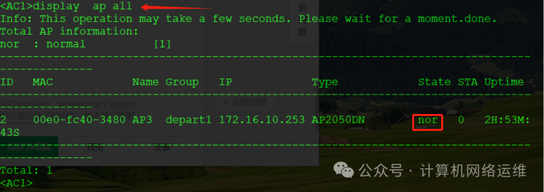
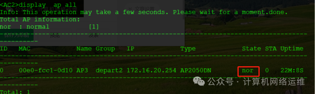
After waiting for a while, check the online status of the AP. The status “nor” indicates that it has successfully come online and is functioning normally!
🎏 Configure AC Layer 3 Roaming
The prerequisite for configuring Layer 3 roaming is that the two ACs can communicate with each other, so configure static routes to achieve this!
[AC1]ip route-static 172.16.200.0 24 172.16.100.252  Configure static route from AC1 to AC2's CAPWAP source interface
[AC2]ip route-static 172.16.100.0 24 172.16.200.252  Configure static route from AC2 to AC1's CAPWAP source interface
🎏 AC1 Roaming Group (Mobility) Configuration!
[AC1-wlan-view]mobility-group name ACMY           Configure the mobility group named ACMY
[AC1-mc-mg-ACMY]member ip-address 172.16.100.254  Add group member AC1's CAPWAP source address
[AC1-mc-mg-ACMY]member ip-address 172.16.200.254  Add group member AC2's CAPWAP source address
🎏 AC2 Roaming Group (Mobility) Configuration!
[AC2-wlan-view]mobility-group name ACMY
[AC2-mc-mg-ACMY]member ip-address 172.16.100.254
[AC2-mc-mg-ACMY]member ip-address 172.16.200.254
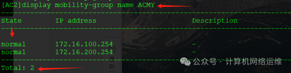
🎏 Check Roaming Group Status
[AC2]display mobility-group name ACMY Check the roaming status of the AC group named ACMY
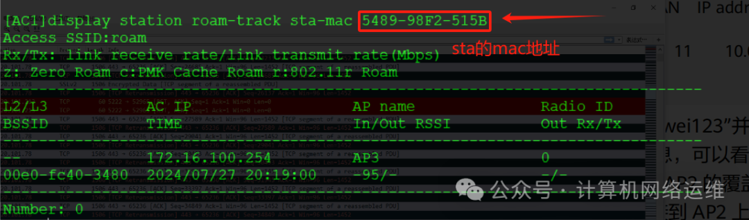
🎏 View Wireless Terminal Information:
[AC1]display station ssid roam View the wireless terminal information connected to the SSID named roam🎏 View STA Roaming Track:
[AC1]display station roam-track sta-mac 5489-98F2-515B
Additionally, I will briefly discuss the NAT configuration of the router. Previously, I talked about the firewall configuration; friends who haven’t seen it can click the link below:Network Engineering Graduation Project – Group Headquarters Network MSTP+VRRP, Achieving Layer 3 Intercommunication with OSPF!Here, I will simply explain how to configure NAT for public access from the router’s perspective!
[AR1-acl-basic-2000]rule 5 permit source 172.16.0.0 0.0.255.255
                    ACL allows addresses 172.16.0.0 with mask 255.255.0.0 to pass through

[AR1-GigabitEthernet0/0/1]nat outbound 2000  Bind ACL 2000 for outbound NAT (firewall easy-ip)
Easy IP on Huawei routers means directly writing ACL to match which subnets need to access the public network!
Configuration for SW1 connecting to the router will not be written here! Writing it again is not meaningful! If you don’t understand, you can first look at the Network Engineering Graduation Project – Group Headquarters Network MSTP+VRRP, Achieving Layer 3 Intercommunication with OSPF!
After configuration, ping 8.8.8.8 from the STA to simulate access to Baidu!
 Thus, this experiment is complete. If there are any errors, please leave a comment. Thank you all!
Recommended Reading:
1:Network Engineering Graduation Project – Branch Network Planning Design Ideas!2:Network Engineering Graduation Project – Group Headquarters Network MSTP+VRRP, Achieving Layer 3 Intercommunication with OSPF!3: Network Engineering Graduation Project – Group Headquarters and Branches Achieving Interconnection via IPsec!4: Network Engineering Graduation Project – Group Headquarters Wireless Network Planning Design, WLAN Configuration Explanation!5: Huawei Device Dual Core VRRP and BFD Interaction!
Click the card above to follow us👆
Reply with the corresponding number to receive Huawei Network Engineer study materials