 (Can be interpreted on behalf of the author, published after proofreading) Submission Channel ↑
 Lithium-ion batteries (LIBs) occupy an important position in the secondary battery market due to their high energy density and flexible usage characteristics. However, their performance still cannot meet the growing energy storage demands, especially in the electric vehicle sector. To enhance the energy and power density of batteries, researchers are committed to developing cathode materials with higher capacity density and operating voltage. Among them, high-nickel layered transition metal oxides NMC (such as LiNi₀.₈Mn₀.₁Co₀.₁O₂, referred to as NMC811) have attracted attention due to their high energy density. However, high-nickel NMC tends to exhibit structural instability, particle cracking, and electrolyte oxidation during cycling, leading to rapid performance degradation of the battery. To address these issues, researchers have attempted to use particle coating technology to improve the cycling stability of the battery.Recently, a team led by Mathieu Morcrette and Matheus Leal de Souza from the University of Picardie Jules Verne in France coupled differential voltage analysis (dV/dQ vs Q) and distribution of relaxation times (DRT) techniques to study the degradation effects of NMC811/Gr coin cells with and without NMC electrode coatings during cycling aging processes, demonstrating their advantages in electrode development. Differential voltage analysis (DVA) can monitor the loss of active material (LAM), chemical changes, and the alignment of the state of charge (SOC) of individual electrode active materials, which are primarily related to lithium inventory loss (LLI). DRT, as a time-domain impedance representation method, can provide high-resolution information on resistance processes, complementing DVA analysis, revealing the kinetic degradation of the battery, and identifying the origins of major resistance processes in the electrodes. Integrating these techniques into aging protocol is a non-invasive method, and the results indicate that lithium ion consumption is the main cause of capacity decay in both types of batteries, while applying a coating reduces or minimizes the LAM and chemical changes of NMC. From the perspective of power decay, the coating slows down the increase in battery impedance (IR), which is mainly related to the resistance processes in the cathode.This achievement was published in the Journal of Power Sources under the title “Coupling differential voltage analysis and distribution of relaxation times I: Evaluating the impact of NMC811 coating in the degradation of NMC811/Gr cells,” with Matheus Leal de Souza as the first author.
(Compiled by Electrochemical Energy, reproduction without permission is prohibited)
【Key Points】
This article focuses on the impact of NMC811 coating on the degradation behavior of NMC811/Gr batteries, revealing the mechanism of the coating’s role in the battery aging process through the coupling of differential voltage analysis (DVA) and distribution of relaxation times (DRT) techniques.
1. Impact of Coating on NMC811 Electrode
The main role of the NMC811 coating is to limit the degradation process of the electrode at high voltages.
– Reducing particle cracking and electrolyte penetration: High-nickel NMC materials undergo anisotropic volume changes during charge and discharge, especially above 4.2 V, where internal stress increases, making particles prone to cracking. Cracking not only increases the contact area between the electrolyte and the electrode but also accelerates the oxidation reaction of the electrolyte, forming insulating by-products (such as spinel and rock salt phases), leading to active material loss (LAM). The coating reduces direct contact between particles and the electrolyte, thereby decreasing electrolyte penetration and reducing particle cracking and by-product formation.
– Inhibiting side reactions at high voltages: The coating can limit the charge and discharge processes of the NMC811 electrode above 4.2 V, reducing the oxidative decomposition of the electrolyte and oxygen release at high voltages, which can lead to the formation of an unstable passivation layer on the electrode surface, further exacerbating electrode degradation.
2. Impact of Coating on Battery Capacity and Impedance
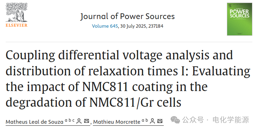
– Capacity retention: The coating significantly improves the capacity retention rate of the battery. The uncoated NMC811/Gr battery has a capacity retention rate of 86% after 210 cycles, while the coated battery retains up to 95% after the same number of cycles. This indicates that the coating effectively reduces the irreversible loss of lithium ions (LLI) and the active material loss (LAM) of NMC811.
– Impedance changes: The coating slows down the rate of increase in battery impedance. The impedance of the uncoated battery significantly increases during aging, especially at high SOC states, where the charge transfer resistance (CTR) of NMC811 rises sharply, leading to a decline in battery performance. In contrast, the impedance increase of the coated battery is more moderate, and even shows a decrease at low SOC states, as the high lithium state of NMC811 gradually moves out of the effective capacity window with increasing LLI, reducing the total impedance of the battery.
3. Application of DVA and DRT Techniques
– DVA analysis: Through differential voltage analysis (DVA), the loss of active material (LAM) and lithium inventory loss (LLI) of the electrode can be accurately monitored. The LAM of NMC811 in the uncoated battery significantly increases during cycling, while the LAM of the coated battery is almost negligible. Additionally, DVA reveals that the coated battery does not exhibit undercharge phenomena of NMC811 at high SOC states, indicating that the coating effectively suppresses side reactions at high voltages.
– DRT analysis: The distribution of relaxation times (DRT) technique is used to analyze the internal resistance processes of the battery. In the aging process of the uncoated battery, the charge transfer resistance (CTR) of NMC811 significantly increases, especially at high SOC states. In contrast, the CTR growth of the coated battery is effectively suppressed, and even shows a downward trend at low SOC states. DRT analysis also indicates that the impedance changes of the coated battery are mainly concentrated in the NMC811 electrode, while the impedance changes of the graphite electrode are relatively small.
4. Comprehensive Effects of Coating
The coating significantly improves the cycling stability and capacity retention of NMC811/Gr batteries by reducing particle cracking, inhibiting side reactions at high voltages, and lowering the reactivity between the electrode and electrolyte. Furthermore, the coating improves the power performance of the battery by reducing the rise in electrode impedance. Although the coating may slightly reduce the initial capacity of the battery, its advantages in long-term cycling processes are more pronounced, especially at high SOC states, where the coating effectively suppresses electrode degradation and extends the battery’s lifespan.
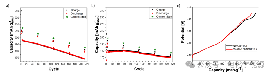
Figure 1: a) Relationship between capacity and cycle number of NMC811/Gr battery, with control steps highlighted in green; b) Relationship between capacity and cycle number of coated NMC811/Gr battery; c) Control step V vs Q curves of NMC811/Li and coated NMC811/Li at low current density (C/20).
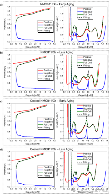
Figure 2: a) Fitting curves of V vs Q and dV/dQ vs Q for the first control step of NMC811/Gr battery; b) Fitting curves of V vs Q and dV/dQ vs Q for the last control step of NMC811/Gr battery; c) Fitting curves of V vs Q and dV/dQ vs Q for the first control step of coated NMC811/Gr battery; d) Fitting curves of V vs Q and dV/dQ vs Q for the last control step of coated NMC811/Gr battery.
Figure 3: Data obtained during control step analysis. a) Electrode mass of NMC811/Gr battery, b) Electrode slip and battery undercharge of NMC811/Gr battery, c) Electrode mass of coated NMC811/Gr battery, d) Electrode slip of coated NMC811/Gr battery.
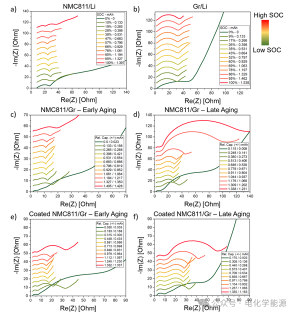
Figure 4: a) Nyquist plot of NMC811/Li battery impedance as SOC changes; b) Nyquist plot of Gr/Li battery impedance as SOC changes; c) Nyquist plot of NMC811/Gr battery impedance during the first control step as the relative capacity of the electrode changes (obtained through V vs Q fitting); d) Nyquist plot of NMC811/Gr battery impedance during the last control step as the relative capacity of the electrode changes; e) Nyquist plot of coated NMC811/Gr battery impedance during the first control step as the relative capacity of the electrode changes; f) Nyquist plot of coated NMC811/Gr battery impedance during the last control step as the relative capacity of the electrode changes. The color bar indicates the battery SOC, and the Nyquist plots of different SOCs are staggered by 5 Ω along the y-axis, except for d), which is staggered by 8 Ω.
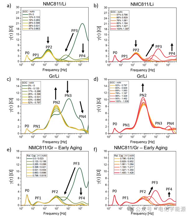
Figure 5: a) DRT peak values of NMC811/Li battery at low SOC as SOC changes; b) DRT peak values of NMC811/Li battery at high SOC as SOC changes; c) DRT peak values of Gr/Li battery at low SOC as SOC changes; d) DRT peak values of Gr/Li battery at high SOC as SOC changes; e) DRT peak values of NMC811/Gr battery at low SOC as the relative capacity of the electrode changes; f) DRT peak values of NMC811/Gr battery at high SOC as the relative capacity of the electrode changes. Arrows indicate the trend of peak height changes, pointing towards the direction of increasing SOC.
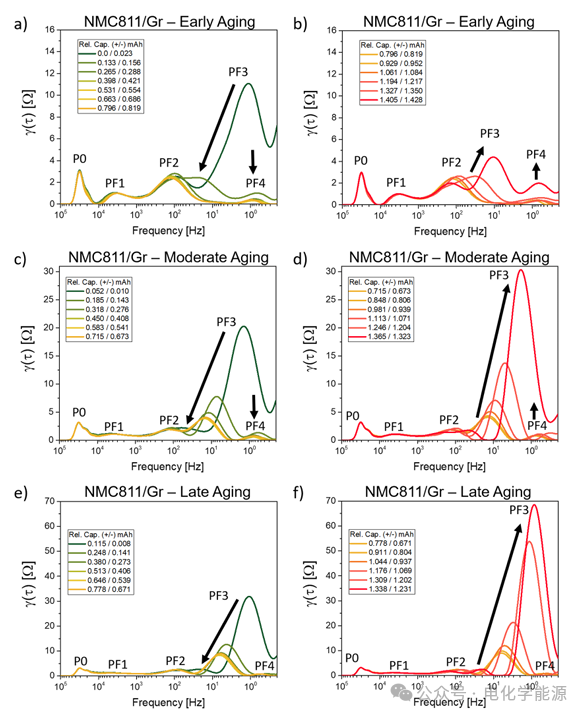
Figure 6: DRT peaks of NMC811/Gr battery during the first control step a) at low SOC and b) at high SOC; DRT peaks during the third control step c) at low SOC and d) at high SOC; DRT peaks during the last control step e) at low SOC and f) at high SOC.
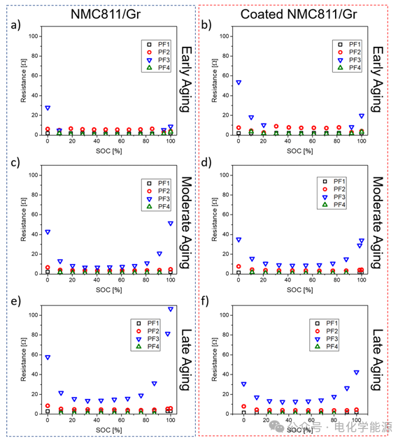
Figure 7: DRT peaks of coated NMC811/Gr battery during the first control step a) at low SOC and b) at high SOC; DRT peaks during the third control step c) at low SOC and d) at high SOC; DRT peaks during the last control step e) at low SOC and f) at high SOC.
Figure 8: a) DRT peak area (impedance) of processes PF1, PF2, PF3, and PF4 during the first control step of NMC811/Gr battery; b) DRT peak area of processes PF1, PF2, PF3, and PF4 during the first control step of coated NMC811/Gr battery; c) DRT peak area of processes PF1, PF2, PF3, and PF4 during the third control step of NMC811/Gr battery; d) DRT peak area of processes PF1, PF2, PF3, and PF4 during the third control step of coated NMC811/Gr battery; e) DRT peak area of processes PF1, PF2, PF3, and PF4 during the last control step of NMC811/Gr battery; f) DRT peak area of processes PF1, PF2, PF3, and PF4 during the last control step of coated NMC811/Gr battery.
【Conclusion】
By comparing NMC811/Gr batteries and coated NMC811/Gr batteries, the impact of cathode coating on battery performance was analyzed using electrochemical techniques. The coupling of differential voltage analysis (DVA) fitting with distribution of relaxation times (DRT) techniques applied to aging protocols has proven to be a non-invasive method that can track the thermodynamic and kinetic degradation effects of each electrode during battery operation. The coating limits the delithiation process of the NMC811 electrode at voltages above 4.2 V. Although this reduces some capacity, it decreases volume changes and particle cracking, thereby reducing electrolyte penetration. Consequently, the coating effectively reduces the transformation of active materials into spinel and rock salt phases, which are the main causes of active material loss (LAM), undercharging at high SOC, and increased charge transfer resistance of the cathode, thus improving the capacity and power retention of the battery during cycling. Based on the material degradation mechanisms reported in the literature, combined with the observed phenomena of NMC811 mass loss and increased charge transfer resistance, the above processes are inferred. Although further confirmation is needed using techniques such as XRD, XPS, and SEM, the coupling analysis of DVA and DRT successfully provides insights into lithium inventory loss (LLI), active material loss (LAM), and impedance rise. One of the detailed insights gained from the methods used is that during aging, the decrease in impedance of the coated NMC811/Gr battery at low SOC is related to the slip of the cathode. This “virtual” power performance enhancement of the battery in the discharge state arises from the gradual exclusion of the high lithium state of NMC811 (high resistance state) from the effective capacity window of the battery with increasing LLI, highlighting the importance of covering different SOCs and accurately measuring electrode slip. The presented electrochemical methods have practical value in assessing the impact of NMC811 coating on battery capacity and impedance at different lifecycle stages and can be conducted under non-invasive and in situ conditions. The DVA fitting and DRT coupling method is a powerful tool in optimizing electrode coatings and can also be used to compare the overall degradation of batteries under different electrolytes, binders, electrode compositions, and cycling conditions. In the next steps, this method will be applied to analyze composite electrode batteries with more complex compositions.
Leal de Souza, M., & Morcrette, M. (2025). Coupling differential voltage analysis and distribution of relaxation times I: Evaluating the impact of NMC811 coating in the degradation of NMC811/Gr cells. Journal of Power Sources, 645, 237184.
https://doi.org/10.1016/j.jpowsour.2025.237184

Like, view, share, and give a one-click triple support!