Introduction

As an industrial control computer, PLCs have a modular structure, flexible configuration, high processing speed, and precise data processing capabilities. PLCs also have good control capabilities for stepper motors, utilizing their high-speed pulse output function or motion control function to achieve control over stepper motors.
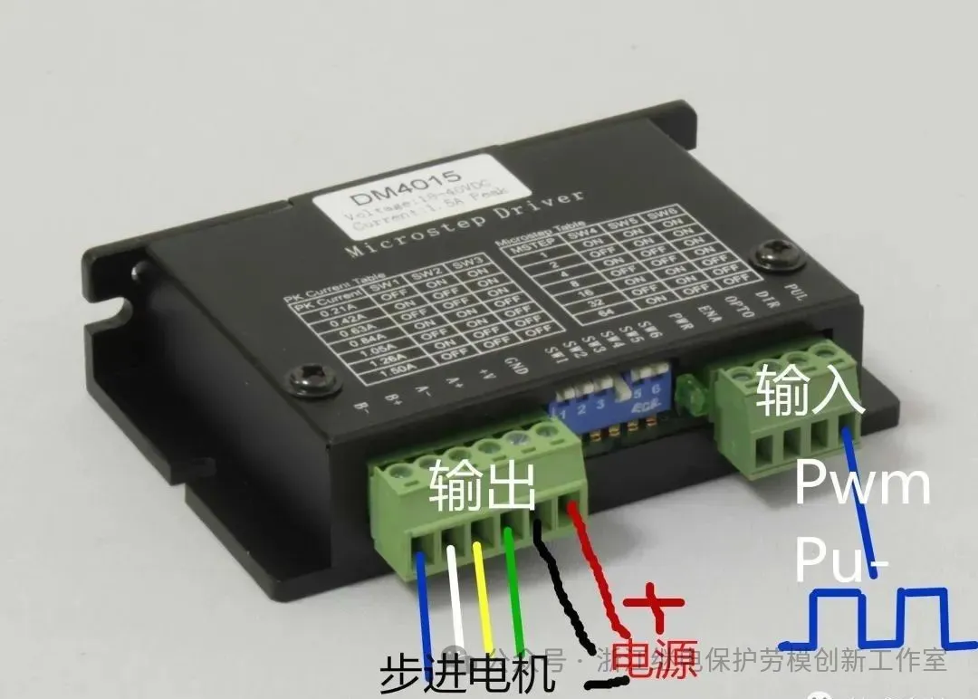
For specific devices where both the distance and speed of movement are determined during operation, I believe that using PLC to control the operation of stepper motors through a stepper motor driver is an ideal technical solution.
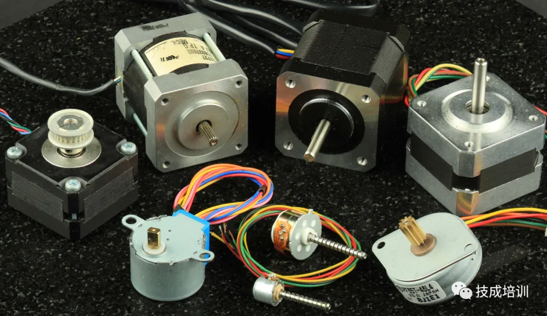
Characteristics of Stepper Motors
(1) The angular displacement of a stepper motor is strictly proportional to the number of input pulses, and there is no cumulative error after the motor completes one rotation, which provides good followability.
(2) The open-loop digital control system composed of the stepper motor and driver circuit is not only very simple and inexpensive but also very reliable. At the same time, it can also be combined with an angle feedback loop to form a high-performance closed-loop digital control system.
(3) The dynamic response is fast, making it easy to start, stop, reverse, and change speeds.
(4) Speed can be smoother adjusted over a considerable range, ensuring high torque even at low speeds.
(5) Stepper motors can only operate when powered by a pulse power supply; they cannot directly use AC or DC power supplies.
The highest stepping frequency at which a stepper motor can respond without losing steps is called the “starting frequency”; similarly, the “stopping frequency” refers to the highest stepping frequency at which the stepper motor does not overshoot the target position when the system control signal is suddenly turned off. The starting frequency, stopping frequency, and output torque of the motor must be compatible with the load’s moment of inertia. With this data, it is possible to effectively control the speed of the stepper motor.
When using PLC to control stepper motors, the system’s pulse equivalent, pulse frequency limit, and maximum pulse count should be calculated using the following formulas to select the appropriate PLC and its corresponding functional modules. The pulse frequency can determine the frequency required for the PLC’s high-speed pulse output, while the pulse count can determine the PLC’s bit width.
Pulse Equivalent = (Stepper Motor Step Angle × Lead) / (360 × Transmission Ratio)
Pulse Frequency Limit = (Moving Speed × Stepper Motor Subdivision Count) / Pulse Equivalent
Maximum Pulse Count = (Moving Distance × Stepper Motor Subdivision Count) / Pulse Equivalent
Pulse Equivalent = (Stepper Motor Step Angle × Lead) / (360 × Transmission Ratio)
Pulse Frequency Limit = (Moving Speed × Stepper Motor Subdivision Count) / Pulse Equivalent
Maximum Pulse Count = (Moving Distance × Stepper Motor Subdivision Count) / Pulse Equivalent
PLC control of stepper motors first requires establishing a coordinate system, which can be set as a relative coordinate system or an absolute coordinate system. The coordinate system settings in DM6629 are as follows: bits 00-03 correspond to pulse output 0, and bits 04-07 correspond to pulse output 1. Setting it to 0 indicates a relative coordinate system; setting it to 1 indicates an absolute coordinate system.
Using PLC to control stepper motors through a stepper driver has made the application of PLCs in stepper motor control more widespread.
For example, during the control process of single-axis and dual-axis movements, parameters such as moving distance, speed, and direction are set on the control panel.
After the PLC reads these set values, it generates pulse and direction signals through calculations to control the stepper motor drive, achieving control over distance, speed, and direction. Furthermore, the system’s operational results have been proven to be reliable, feasible, and effective through practical measurements.