Click the blue words to follow, follow me to learn embedded systems.Today I developed with Cortex-M4, using STM32MP157, which is a dual-core chip integrating M4 and A7. Today mainly involves the installation of CubeIDE, which is quite simple, but there are a few key points to note, let me summarize:
01
STM32CubeIDE Official Download Link
First is the download link, which can be obtained directly from the ST official website:https://www.st.com/zh/development-tools/stm32cubeide.html
02
STM32CubeIDE Installation Notes
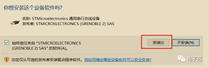
During installation, do not install it in a Chinese path.During the installation process, you will be prompted to install the serial bus device, which is necessary to install the STLink driver, as it is needed when programming, so it must be installed. After installation, remember to check if STLINK appears in Device Manager.
03
STM32CubeIDE Code Generation Notes
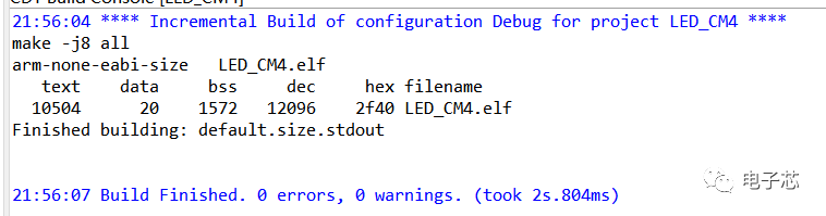
This part mainly involves practical issues. After generating the code, there were no problems with compilation, and the compilation result is as follows. You can compare it with your own compilation information.
04
Process of Solving Programming Issues
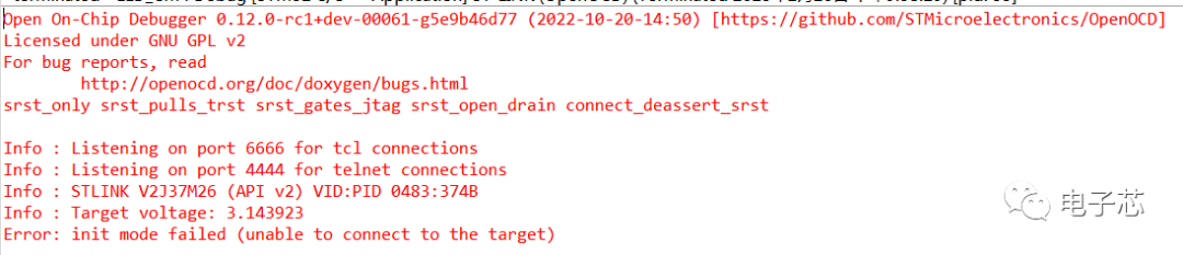
However, after connecting the STLINK, the program did not burn onto the development board.(Click to purchase the development board) This was a pitfall that took a while to resolve.
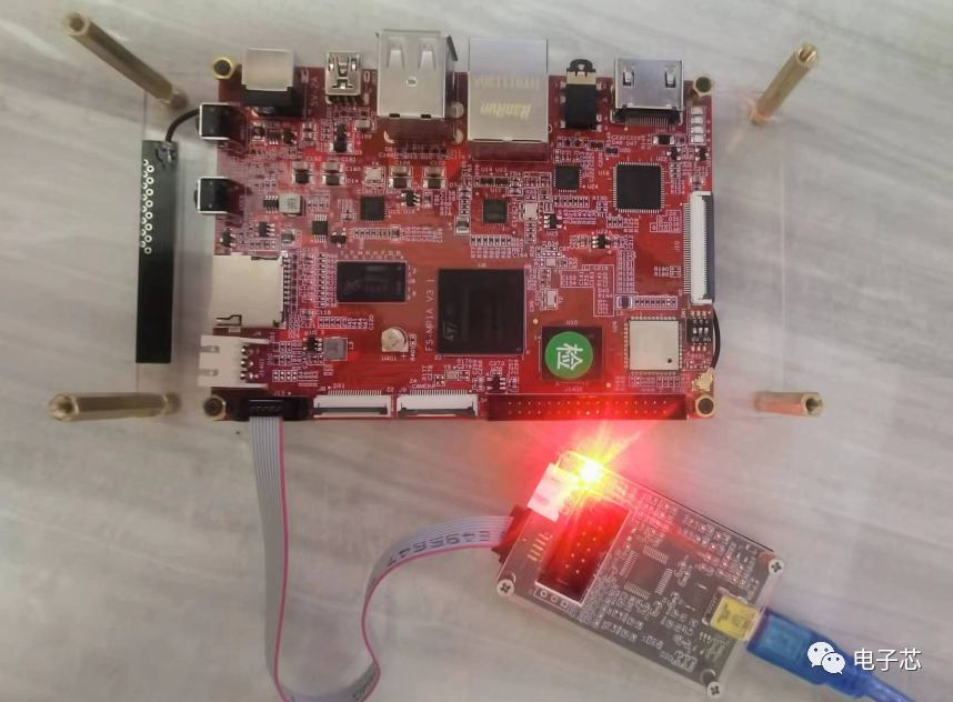
Upon observing the development board, I found that it was only connected to the computer through STLINK. There were no other connections. As a developer with many years of experience (forgive me for calling myself that  ), I felt that the development board seemed to be “dead”. Therefore, I wanted to check whether the development board was powered.
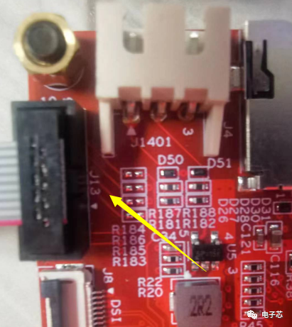
So I opened the circuit diagram of the development board. Because the development board only has one connection, which is STLINK, located at port J13, it can be seen on the development board. At the same time, I checked the silk screen diagram to confirm that J13 is indeed the STLINK interface.
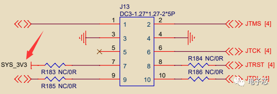
Next, looking at the J13 interface in the circuit diagram, I can see that there is a power supply SYS_3V3, connected through a 0Ω resistor R183, which is a 3.3V power supply. It might be powered through STLINK? (Just a guess, needs further confirmation)
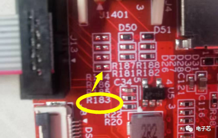
Then I found that R183 on the development board was not soldered, so even if pin 7 of J13 could supply power, it could not be input into the development board. Therefore, the development board had no power at all, and it was a miracle that it could burn the program.
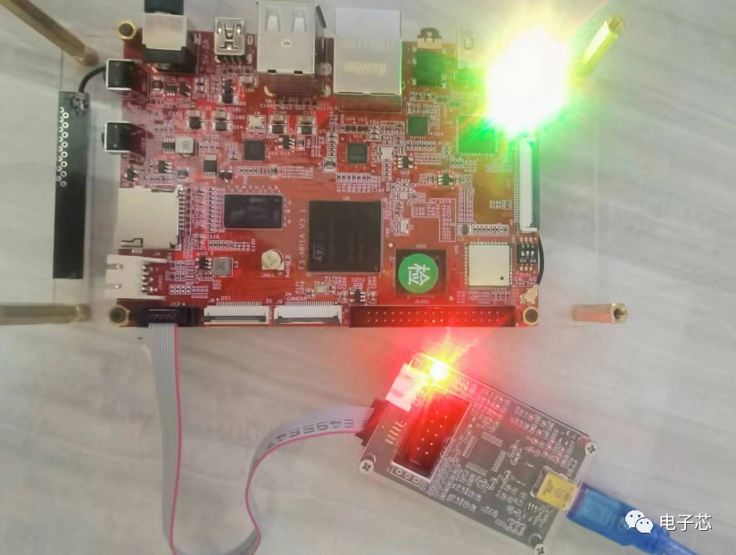
Therefore, I found the power supply interface and connected the adapter for power. You can see the power indicator light up. The code was successfully burned again and ran.
Additionally, I share this tutorial so everyone can learn on their own and compare with me to see who progresses faster.  Link:https://pan.baidu.com/s/19eOGSw7I1sr7BVVsZRMyIQ?pwd=8afbExtraction code: 8afbFor those who want to start, you can check out my beginner’s three-piece course: “C Language Programming, Microcontroller Programming, Circuit Design Schematics PCB”, “Advanced Learning Kit”
Selected Articles from Previous Issues
☉ This is the core of microcontroller programming, and you will understand the secrets of microcontroller programming after reading it.☉ The difference between microcontrollers and PLCs, which one is more difficult?☉ Do you really understand embedded systems? What exactly is embedded?☉ How does everyone find chip datasheets? Are the manuals from unofficial sources accurate?☉ Learning the differences between 51 microcontrollers and ARM microcontrollers, this is the reason why you can’t use ARM microcontrollers.☉ How to take private jobs