Required Materials:
| 1 | Arduino UNO Development Board x1 |
| 2 | Breadboard x1 |
| 3 | LED Bulb x1 |
| 4 | Photoresistor x1 |
| 5 | 220Ω Resistor x1 (Color bands: Red-Red-Brown) |
| 6 | 10kΩ Resistor x1 |
| 7 | Several Male-to-Male Dupont Wires |
| 8 | USB Data Cable (for connecting Arduino to computer) x1 |
1. Project Overview This lesson will guide you on how to use a photoresistor and Arduino to create a system that automatically controls an LED based on the intensity of ambient light. The LED will turn on when the environment gets darker and turn off when the environment gets brighter.2. What is a Photoresistor? A photoresistor (Light Dependent Resistor, LDR) is a type ofphotoelectric device whose resistance changes with the intensity of incident light. When the light intensity increases, the resistance decreases; when the light intensity decreases, the resistance increases. Photoresistors are widely used in various photoelectric control systems, such as automatic doors and light control switches.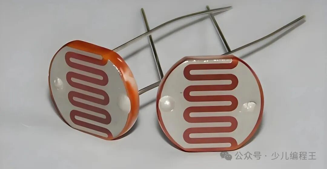
Working Principle
-
Semiconductor Characteristics: The photoresistor is made of semiconductor materials (such as Cadmium Sulfide, CdS).
-
Photoelectric Effect: When photons strike the semiconductor, they excite electrons to jump from the valence band to the conduction band, creating electron-hole pairs.
-
Change in Conductivity: The generated charge carriers increase the conductivity of the material, thereby reducing the resistance.
-
Response Characteristics:
-
Light Intensity ↑ → Number of Charge Carriers ↑ → Resistance ↓
-
Light Intensity ↓ → Number of Charge Carriers ↓ → Resistance ↑
3. Circuit Connection
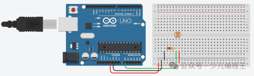
Photoresistor Section
-
Connect one end of the photoresistor to the 5V pin of the Arduino.
-
Connect the other end of the photoresistor to the 10kΩ resistor.
-
Connect the other end of the 10kΩ resistor to GND.
-
Connect the junction of the photoresistor and the 10kΩ resistor to the A0 pin of the Arduino (analog input).
LED Section
-
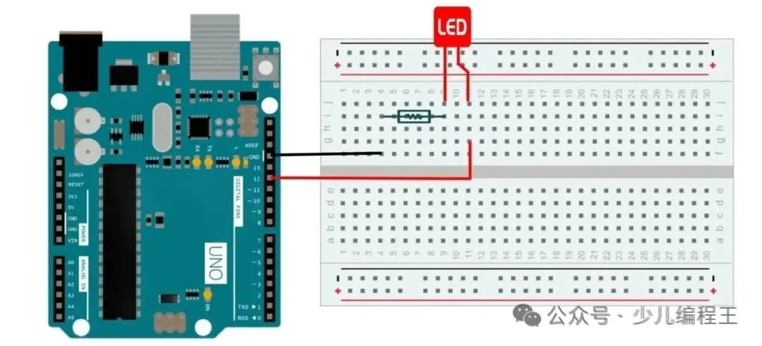
Connect the long leg (anode) of the LED to digital pin 9 of the Arduino through a 220Ω resistor.
-
Connect the short leg (cathode) of the LED to GND.
 4. Practical Exercise – Programming the Light-Controlled LED
1. Basic Version (Switch Control)
// Define pinsconst int lightSensorPin = A0;  // Analog pin connected to the photoresistorconst int ledPin = 9;           // Digital pin connected to the LED
// Variable definitionint sensorValue = 0;            // Store the reading from the photoresistorint threshold = 500;            // Light threshold, adjustable based on actual conditions
void setup() {  // Initialize serial communication  Serial.begin(9600);
  // Set LED pin as output  pinMode(ledPin, OUTPUT);
  // Initially turn off the LED  digitalWrite(ledPin, LOW);}
void loop() {  // Read the value from the photoresistor (0-1023)  sensorValue = analogRead(lightSensorPin);
  // Display the reading in the serial monitor (optional, for debugging)  Serial.print("Light Sensor Reading: ");  Serial.println(sensorValue);
  // Control the LED based on light intensity  if (sensorValue < threshold) {    // Dark environment, turn on LED    digitalWrite(ledPin, HIGH);    Serial.println("Environment is dark, LED is ON");  } else {    // Bright environment, turn off LED    digitalWrite(ledPin, LOW);    Serial.println("Environment is bright, LED is OFF");  }
  // Delay for a while before the next reading  delay(500);}
2. Advanced Version (With Fade Effect)
const int lightSensorPin = A0;const int ledPin = 9;
int sensorValue = 0;int minLight = 200;    // Minimum light value (darkest condition)int maxLight = 800;    // Maximum light value (brightest condition)
void setup() {  Serial.begin(9600);  pinMode(ledPin, OUTPUT);}
void loop() {  sensorValue = analogRead(lightSensorPin);
  // Map the light reading to LED brightness (0-255)  int ledBrightness = map(sensorValue, minLight, maxLight, 255, 0);
  // Constrain the brightness value within valid range  ledBrightness = constrain(ledBrightness, 0, 255);
  // Use PWM to control LED brightness  analogWrite(ledPin, ledBrightness);
  Serial.print("Light Value: ");  Serial.print(sensorValue);  Serial.print(" | LED Brightness: ");  Serial.println(ledBrightness);
  delay(100);}
5. Results Display5.1 Compile and Upload the Program
-
Connect the Arduino to the computer using a USB cable.
-
Select the correct board type in the Arduino IDE (
<span>Tools -> Board -> Arduino Uno</span>) and port (<span>Tools -> Port -> ...</span>). -
Click the “Upload” button (right arrow) in the upper left corner.
-
Wait for the upload to succeed.
5.2 Demonstration Effect6. Review of Previous Content【Introduction to Scratch】Lesson 1 – Installing Arduino IDE Software【Introduction to Arduino】Lesson 2 – Lighting Up an LED【Introduction to Arduino】Lesson 3 – Lighting Up Your First External Light【Introduction to Arduino】Lesson 4 – Running Lights【Introduction to Arduino】Lesson 5 – Breathing Light【Introduction to Arduino】Lesson 6 – Button Switch Light【Introduction to Arduino】Lesson 7 – Adjustable Light【Introduction to Arduino】Lesson 8 – Memory Master Game【Introduction to Arduino】Lesson 9 – Rainbow Light