1 Introduction
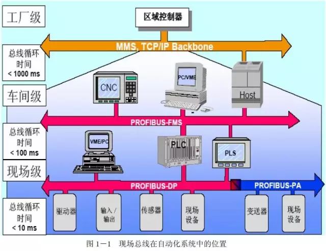
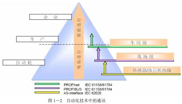
With the rapid growth of decentralized structures in manufacturing automation and process automation, the application of field buses is becoming increasingly widespread. It facilitates data transmission between digital and analog input/output modules, intelligent signal devices, and process control devices with PLCs/PCs, dispersing I/O channels to field devices located nearby as required. This reduces the overall engineering costs, assembly costs, hardware costs, equipment commissioning, and maintenance costs to a minimum. Standardized field buses have “open” communication interfaces and “transparent” communication protocols, allowing users to choose decentralized I/O devices and field devices produced by different manufacturers. The PROFIBUS field bus meets the important requirements for data accessibility at the production process field level. On one hand, PROFIBUS covers the communication requirements of sensors/actuators (AS-I level), and on the other hand, it possesses all network communication functions at the unit level. Therefore, the PROFIBUS bus is particularly suitable for fast, time-critical applications and complex communication tasks in the field of factory automation and process automation.
The field communication bus links the system and programmable controllers. Field equipment monitors unit-level commands, sends signals, and transmits them to the system. Generally speaking, the amount of data transmitted is small, and the messages are short, but the response time is short. Typically, hierarchical communication is used, where several field devices communicate with a master station. PROFIBUS-DP is used for fast, cyclic data exchange of field devices, while PROFIBUS-PA is used for process automation in intrinsically safe systems.
2 Basic Principles
1.ISO/OSI(Open Systems Interconnection Reference
Model)Model
In order to communicate effectively and accurately, certain rules and necessary transmission interfaces are used in communication protocols. The International Organization for Standardization (ISO) developed the OSI reference model in 1983, which defines all elements, structures, and tasks required for communication and organizes them into seven layers. In the communication process, each layer must perform the specified functions. If a communication system does not require certain specific functions, the corresponding layers can be omitted. The ISO/OSI communication standard model is organized into seven layers and divided into two categories. One category is user-oriented, covering layers five through seven, while the other is network-oriented, covering layers one through four. Layers one through four describe the transmission of data from one place to another, while layers five through seven provide users with appropriate means to access network systems. The PROFIBUS protocol adopts the first, second, and seventh layers of the ISO/OSI model.
Table 2-1 ISO/OSI Model
Layer
Relation
Function
7
Application Layer
Interface for application programs facing application requirements (read, write)
6
Presentation Layer
Data representation method for analysis and interpretation in the next layer (encoding)
5
Session Layer
Establishing and clearing temporary station connections; synchronizing communication processes
4
Transport Layer
Controls data transmission for layer 5 (transmission error, fragmentation into information packets)
3
Network Layer
Establishing and clearing connections, avoiding network congestion
2
Data Link Layer
Describes bus access protocol for data security (media access control)
1
Physical Layer
Defines media (hardware), data encoding, and transmission speed
2.PROFIBUS Types
PROFIBUS complies with IEC 61158/EN50170 Volume 2 standards, and can be classified according to different transmission media and data processing methods as follows:
Transmission Media:
● Electrical Network: Shielded twisted pair cables
● Optical Fiber Network: Optical fiber cables (glass, PCF, and plastic)
● Infrared Wireless Transmission: Infrared
Data Information Processing Methods:
● Data Communication: S7 communication, standard FMS communication, PG/OP communication, OPC server, etc.
● Process and Field Communication: PROFIBUS DP, PROFIBUS PA
3.PROFIBUS Topology
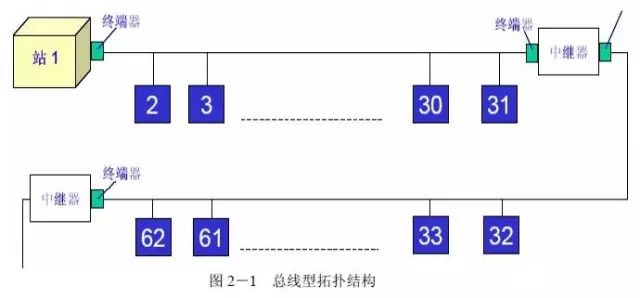
PROFIBUS electrical networks support linear, tree, and star topologies; optical fiber networks support linear, tree, and ring topologies; wireless connection networks support point-to-point and point-to-multipoint topologies. A PROFIBUS segment can have up to 32 stations. If a PROFIBUS network exceeds 32 stations, RS485 repeaters are required for separation. RS485 repeaters are active network components that do not have a station address themselves, but are counted in the total number of stations in each segment (similar devices include OLMs for PROFIBUS optical fiber link modules). For tree structures, if different types of components are connected, they can be connected through converters (routers, bridges, gateways, etc.). Each PROFIBUS bus connector is equipped with terminal resistors, which are placed at both ends of the PROFIBUS bus and activated by supplying power to the terminal resistors through the stations.
The following figure shows the bus topology:
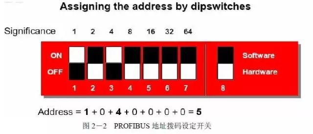
4.PROFIBUS Address Setting
In a PROFIBUS network, the position setting of the master station and each slave station can be set through hardware (dip switches) or software. After setting the PROFIBUS address with dip switches, the device must be powered on again to activate the address. When there are no dip switches on the device, the PROFIBUS address can also be set through parameters or related software, such as SIMATIC S7 HW Config. Typically, the default value set by the software is always 126. It is important to note that when the PROFIBUS address is set both through hardware dip switches and software, the hardware address setting has a higher priority.
5.PROFIBUS Addressing Principles
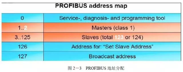
In the PROFIBUS bus network system, the address allocation of each master station and slave station usually follows the following rules (recommended):
● In most configuration software, address “0” is reserved for services, diagnostic devices, and programming PCs.
● Address “1” is basically reserved for the master station. Even if there is only one master station on the network, the addressing of slave stations is best started from “3”, especially for PA devices.
● Address “126” is reserved for pre-setting a new slave address.
● Address “127” is generally used as a broadcast address. If a master station sends a message to address “127”, all slave stations on the network can receive the message, but do not respond.
Therefore, in practice, there can be a maximum of 124 slave stations on a PROFIBUS network bus.
6.PROFIBUS Token Passing
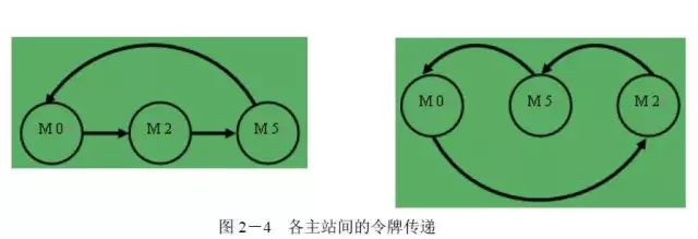
PROFIBUS bus access control specifies when bus nodes can send data and that only one node has the right to send at any given time. The token passing rule is used to satisfy the definition of bus access control. The token, which is the right to access the transmission medium, is passed between active bus nodes using a special token message. If a node possesses the token, it can send messages until the so-called token holding time (according to configuration) ends. If the token holding time ends, that station is only allowed to send high-priority messages. If a node has no messages to send, it passes the token to the next node in the logical ring. The active node with the highest station address (HSA) is an exception; it only passes the token to the active node with the lowest bus address to close the logical token ring again. PROFIBUS is a token ring network, with the token passed from stations with low addresses to those with high addresses, and after reaching the highest PROFIBUS station address, it is passed back to the lowest station address. The token passing is limited to enabled master stations and is independent of the topological arrangement of master stations, such as: DP master stations.
Token scheduling ensures that each master station has sufficient time to complete its communication tasks. Users organize the total target token rotation time (TTR) into the communication task accounts of all master stations. Each master station calculates the time (TTH) it has to complete its communication task after receiving the token using the following formula:
TTH=TTR-TRR
TTH: Token holding time
TTR: Target token rotation time
TRR: Actual token rotation time
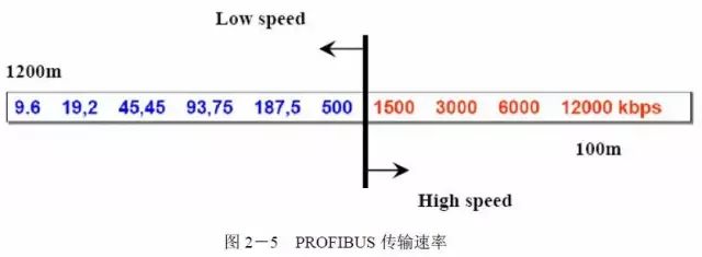
7.PROFIBUS Transmission Rate (baudrate )
In the ISO/OSI reference model, the first layer defines the “physical” data transmission method, including encoding types and transmission standards used (e.g., RS485). PROFIBUS provides various types of transmission technologies for the first layer. All types are based on international standards and are included in the PROFIBUS sections of IEC 61158 and IEC61784.
RS485 transmission technology is a simple and low-cost transmission technology primarily used for tasks requiring high transmission rates. It uses shielded twisted copper cables with a pair of wires. RS485 transmission technology allows users to choose transmission rates between 9.6Kbit/s to 12Mbit/s. When commissioning the system, all stations on the bus should select the same transmission speed. The maximum number of stations that can be connected in each bus segment depends on the transmission rate. In PROFIBUS networks, most slave stations can automatically detect the bus transmission rate. It is noteworthy that some older products do not support a transmission rate of 45.45Kbit/s.
8.PROFIBUS Communication Protocol
PROFIBUS provides three types of communication protocols: FMS, DP, PA.
PROFIBUS FMS: PROFIBUS FMS (Fieldbus Message Specification) provides transmission services for structured data (FMS protocol). It uses the first, second, and seventh layers of the OSI reference model. FMS handles data communication at the unit level (PLC and PC), providing great flexibility for solving complex communication tasks.
PROFIBUS DP: PROFIBUS DP is a standardized interface for the transmission of process input and process output data between SIMATIC-S7/M7/C7 stations and field devices (DP slaves). It uses the first and second layers, and this streamlined structure ensures high-speed data transmission, particularly suitable for communication between field-level automation systems (programmable controllers) and decentralized I/O devices. PROFIBUS-DP primarily focuses on factory automation, using RS485 transmission technology with a transmission rate of up to 12Mbit/sec.
PROFIBUS PA: PROFIBUS PA is specially designed for process handling and allows sensors/actuators to connect to shared field bus cables (can also be used in hazardous areas).
PROFIBUS PA uses the extended PROFIBUS DP protocol for data transmission. In addition, it implements the PA device specification that defines the characteristics of field devices. The transmission technology is based on IEC1158-2[7] standards, ensuring intrinsic safety and powering field devices through the bus. Using DP/PA couplers and DP/PA LINK makes it easy to integrate PA devices into the PROFIBUS-DP network. PROFIBUS-PA primarily focuses on process automation, typically using MBP-IS transmission technology, communication protocol DP-V1 version, and application specifications “PA device specifications.” MBP transmission technology (Manchester Coded, Bus Powered) is used for applications requiring devices to be powered by the bus and intrinsically safe for process automation.
9.DP Master and Slave Device Types
● Class 1 DP Master (DPM1)
DPM1 consists of central control stations (e.g., SIMATIC S5, S7, and SIMADYN D) that cyclically exchange information with decentralized slaves within a specified message cycle. DPM1 has active bus access rights, allowing it to read measurement data (input) from field devices and write set values (output) to actuators at fixed time points.
● Class 2 DP Master (DPM2)
Class 2 masters are mainly programming and monitoring stations, primarily used for system maintenance and diagnostics, configuring connected devices, starting, running monitoring systems, and requesting device status, etc. DPM2 does not need to be fixedly connected to the bus system and also has active bus access rights.
● Slave Stations
DP slave stations are peripheral devices, such as I/O devices, drives, HMIs, valves, transmitters, etc. They read process information or intervene in the process with output information. From a communication perspective, slave stations are passive devices that only respond directly to requests.
10.DP Communication Protocol
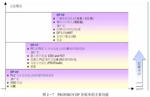
The DP (Decentralized Peripherals) communication protocol is designed for fast data exchange at the field level. As mentioned earlier, the bus cycle time at the field level is less than 10ms. In field communication, central programmable controllers (such as PLCs, PCs, or process control systems) communicate with decentralized field devices (such as I/O, drives, valves, transmitters, or analyzers) through fast serial connections. The data exchange with decentralized field devices is mainly cyclic data exchange. The communication functions required for cyclic data exchange are specified through the basic DP functions (version DP-V0). Based on the specific needs of various application fields, these basic DP functions have been gradually expanded with special functionalities, resulting in three versions: DP-V0, DP-V1, and DP-V2, each with its own key features. The distinction of versions mainly reflects the chronological order of normative work completed in response to the growing application demands.
The key contents of the three versions are as follows:
DP-V0 provides basic DP functions, including bus access methods, cyclic data exchange, diagnostic functions (station diagnostics, module diagnostics, and specific channel diagnostics), protection functions, configuration and control functions via the network, synchronization and locking functions, cyclic data transmission between DPM1 and DP slaves, and cyclic data transmission between DPM1 and system configuration devices.
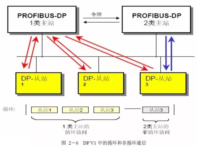
DP-V1 includes functions added based on process automation needs, particularly non-cyclic data communications for parameter assignment, operation, visualization of intelligent field devices, and alarm processing (similar to cyclic user data communication). This allows online access to stations using engineering tools. Additionally, DP-V1 has three additional alarm types: status alarms, refresh alarms, and manufacturer-specific alarms.
DP-V2 includes the following functions primarily added based on drive technology needs:
● Slave-to-Slave Communication (DXB)
This function allows direct and time-saving communication between slaves using broadcast communication without the need to go through the master station.
● Isochronous Mode
Isochronous mode enables clock synchronization control between master and slave stations, independent of bus load. It allows for high-precision positioning processing with clock errors of less than 1 microsecond. A special life marker (sign of life) allows for synchronization monitoring.
● Clock Control
This function (real-time master station sends time stamps to all slave stations using new connectionless MS3 services) synchronizes all stations with the system time, with an error of less than 1 millisecond. Clock control is very useful for obtaining timing functionality in multi-master networks. It can also facilitate fault diagnosis and sequential event logging.
DP V2 also features data uploading and downloading as well as function calls. Due to the added functionalities mentioned above, DP-V2 can also be implemented as a drive bus for controlling rapid motion sequencing of drive axes. Various versions of DP are detailed in IEC 61158, as shown in Figure 2-7.
11.PROFIBUS Network Application Technology
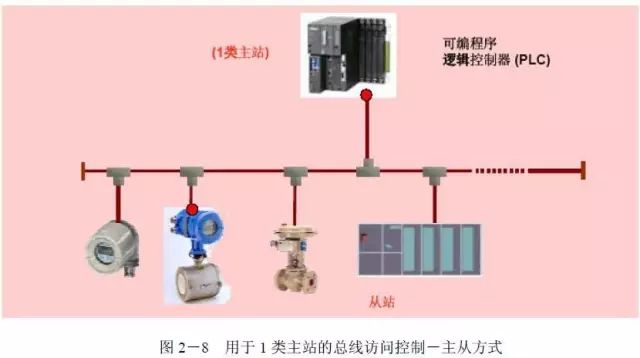
In a PROFIBUS network, there are several passive nodes (slave stations), while its logical token only contains one active node (master station), making this network a pure master-slave system. The typical PROFIBUS-DP bus configuration is based on this bus access procedure, where a master station polls multiple slave stations. PROFIBUS-DP is the most widely used in all PROFIBUS applications and can connect devices from different manufacturers that comply with the PROFIBUS-DP protocol. In a DP network, a slave station can only be controlled by one master station, which is its Class 1 master station; if there are programming and operation panels controlling the slave station on the network, these programming and operation panels are its Class 2 master stations.
In another scenario, in a multi-master network, a slave station has only one Class 1 master station, which can perform sending and receiving data operations with the slave station, while other master stations can only selectively receive data sent from the slave station to the Class 1 master station. Such a master station is also a Class 2 master station for that slave station, which does not directly control the slave station. PROFIBUS master stations can be CPUs with integrated DP ports, or S7-300 stations expanded with CP342-5, IM467; S7-400 stations expanded with CP443-5 Extend. Upper-level machines with communication cards CP5411, CP5511, CP5611, CP5412, CP5613 can also serve as PROFIBUS-DP master stations. These communication cards can act as PROFIBUS network cards and support the PROFIBUS protocol when integrated with PROFIBUS drivers. PROFIBUS slave stations include ET200 series, speed control devices, S7-200/300/400 stations, and third-party devices.
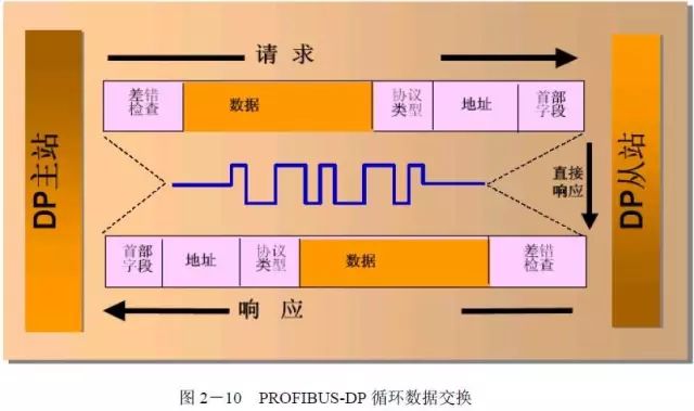
In the cyclic data exchange of PROFIBUS-DP, the time taken by all slave stations to process the messages is called a cycle. The duration of the cycle depends on the baud rate of data transmission, the number of slave stations, and the capacity of net data. Each slave station can transmit up to 244 bytes of data at a time.
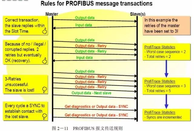
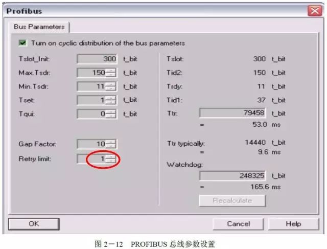
Under normal circumstances, a slave station will respond within the set time cycle after receiving a message sent by the master station. For messages sent by the master station, if the slave station does not respond within the set “retry” count, the master station will send the message to the next slave station and simultaneously generate a SYNC signal. The number of times the master station resends messages can be set in the PROFIBUS bus parameter settings in STEP 7, as shown in the figure below.