PROFIBUS Transmission Technology (Physical Layer) and DP Communication
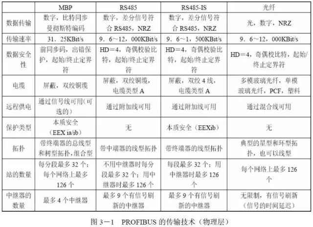
In the ISO/OSI reference model, the first layer defines the “physical” methods of data transmission. This includes encoding types and the transmission standards used (e.g., RS 485). PROFIBUS provides various transmission technologies for the first layer: RS 485, RS 485-IS, MBP, and fiber optic transmission technology. Traditional DP is a high-speed communication system using RS 485 or fiber optic transmission technology, initially aimed at manufacturing automation applications. To enable its application in process automation, the intrinsically safe RS 485-IS transmission technology was developed. It is based on IEC61158-2 and provides excellent explosion-proof functionality, widely used in hazardous areas. RS 485-IS can be easily integrated into systems with existing PROFIBUS DP RS 485 devices, meaning it can utilize the entire infrastructure of PROFIBUS. Fieldbus isolation repeaters with integrated isolation barriers are used to integrate RS 485-IS into existing PROFIBUS systems. Additionally, there is a PROFIBUS PA communication system for process automation systems and field devices, which uses the extended protocol of PROFIBUS DP for data transmission. It employs a special physical layer compliant with the international standard IEC61158-2, characterized by “Manchester Coded Bus Powered” and meets the requirements of process engineering (e.g., remote power supply and intrinsic safety). All of the above transmission technologies are based on international standards and are included in the PROFIBUS sections of IEC 61158 and IEC 61784.
1. RS 485 Transmission Characteristics
PROFIBUS transmission technology describes the physical, electrical, and optical characteristics of the device interface. In practical field applications, 90% use RS 485 transmission technology. It has the following characteristics:
RS 485,High Speed (H1):
● Asynchronous NRZ transmission based on RS 485
● Baud rate from 9.6Kbit/s to 12Mbit/s, optional.
● Twisted shielded cable.
● 32 stations per segment, allowing up to 126 stations.
● Distance: 12Mbit/s=100m; 1.5Mbit/s=200m; ≤187.5Kbit/s=1000m.
● With repeaters, the distance can be extended to 10 kilometers.
● 9-pin D-type connector
MBP,Low Speed (H2):
● Synchronously Manchester coded, 31.25kbit/s
● Intrinsic safety (optional) and bus-powered (optional)
● Shielded or unshielded twisted pair cable
● Distance up to 1900 meters, extendable to 10 kilometers with repeaters
● Up to 126 stations, with 10 to 32 devices per segment (depending on Ex-type and power consumption)
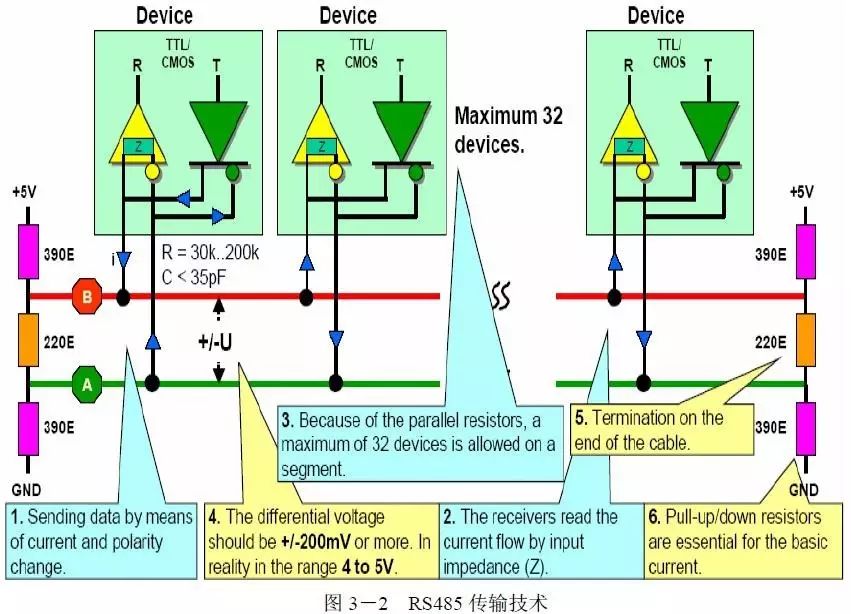
2. RS 485 Transmission Technology
(1) The sender defines the logical “0” and “1” signal levels by changing the direction of the current to send data.
(2) The receiver receives data by reading the different directions of current flowing through the input resistance.
(3) Due to the parallel connection of sender and receiver resistors, it is equivalent to the load on the bus. Thus, a maximum of 32 stations can be connected per bus segment.
(4) The differential voltage between A and B should be greater than ±200mv, and the actual measurement should be between 4 to 5V.
(5) At both the beginning and end of each bus segment, a resistor network must be activated, known as the termination resistor, which we usually call the bus terminator. Each bus terminator has a continuous power supply to ensure error-free data transmission. Siemens standard bus connectors include bus terminators.
(6) Grounding resistance ensures that when there is no data transmission on the bus, the high-level signal remains on the bus to prevent noise interference. This is especially important during high-speed data transmission to ensure normal bus communication.
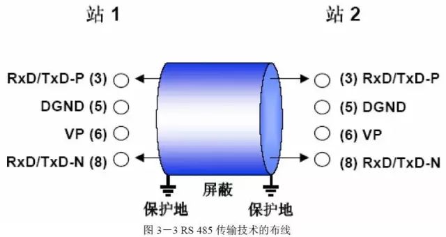
3. RS 485 Transmission Technology Wiring
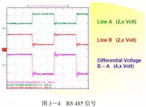
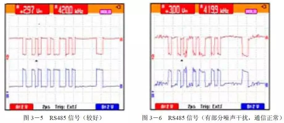
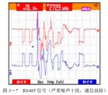
4. RS 485 Signal
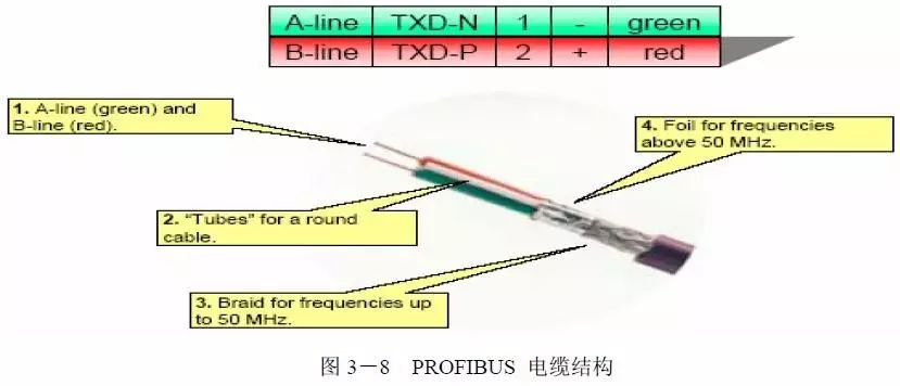
RS 485 transmission technology transmits PROFIBUS signals through shielded twisted data cable core wire A (green) and core wire B (red). In the above figure, Line A represents the signal on the green core wire (which can be measured using an oscilloscope between data line A and data line ground), and Line B represents the signal on the red core wire (which can be measured using an oscilloscope between data line B and data line ground). Line B – Line A is the actual measured differential RS485 signal (which can be measured using an oscilloscope between data line B and data line A), which is the actual signal waveform of PROFIBUS. The voltage difference between the high level and low level measured between Line B and Line A should be between 4V and 7V. The positive and negative voltage values should be approximately equal. In practice, the difference between these two values is about 0.5V. The following figure shows some typical PROFIBUS signal waveforms.
5. PROFIBUS Cable Specification Requirements—RS485
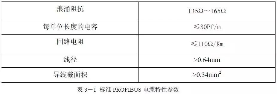
The standard PROFIBUS cable consists of a purple outer shell, twisted copper cable, supporting conduit, a shielded braided layer (shielding ≤50MHZ signals), and a shielded aluminum foil layer (shielding >50MHZ signals).
In the PROFIBUS standard, the bus cable is specified as “Cable Type A” and must comply with the following characteristic parameters.
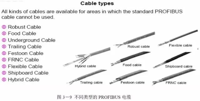
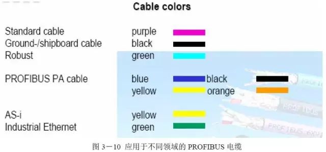
In addition to the standard purple PROFIBUS DP cable, PROFIBUS offers many different types of cables that meet the characteristics of specific fields for various process automation and factory automation applications.
⊙ Reinforced (Robust) Cable
⊙ For Food and Pharmaceutical Manufacturing (completely different from the standard bus cable outer shell)
⊙ Can be directly buried (Underground) cable, with additional protective sheath
⊙ Dragging (Trailing) cable, for incidental or intermittent dragging of mechanical parts
⊙ Festooned cable, which has additional tension relief elements compared to trailing cables
⊙ Standard bus cable with halogen-free outer shell (FRNC)
⊙ Super flexible (Flexible) cable, for frequently dragged mechanical parts
⊙ Shipboard cable, resistant to seawater corrosion
⊙ Hybrid cable
In these different applications, PROFIBUS cables usually have clear color markings.
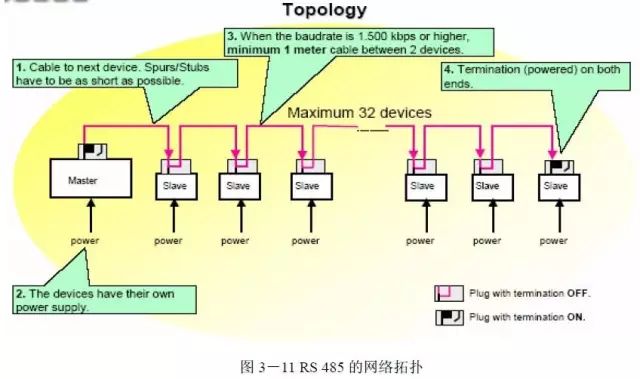
6. RS 485 Network Topology
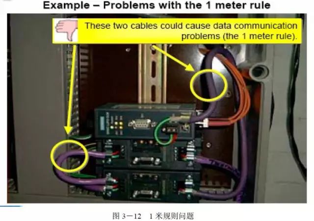
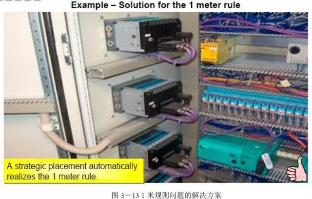
In a PROFIBUS network, all devices are connected in a bus structure, with a maximum of 32 stations (master or slave) connected in one bus segment. Each bus segment has an active bus terminator at both ends. Each bus terminator has its own continuous power supply to ensure error-free operation. Bus terminators are usually integrated into the devices or connectors. If there are more than 32 stations or if the network area needs to be expanded, repeaters must be used to connect the various bus segments. Repeaters do not have station addresses, but they are counted in the number of stations per segment. When the baud rate is below 1500 kbps, the branch lines connected between two stations and the short-circuit lines between the stations and the repeaters should be kept as short as possible. When the baud rate exceeds 1500 kbps, the branch line between two stations should not be less than 1 meter.
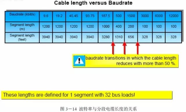
The transmission baud rate of the PROFIBUS bus ranges from 9.6Kbit/s to 12Mbit/s. In the early days, some devices only supported up to 1.5Mbit/s. Now, most devices can reach 12Mbit/s, and the bus length is related to the transmission rate. The general rule is that the higher the transmission baud rate, the shorter the bus length, which is more susceptible to electromagnetic interference. From the following figure, it can be seen that when the baud rate is between 187.5Kbit/s and 3000Kbit/s, the bus length is almost halved with the increase of baud rate. The maximum segment length based on transmission baud rate is shown in Figure 3-14.
The PROFIBUS bus cable matches the terminal resistors of the PROFIBUS bus connectors and is equipped with axial inductance to eliminate wire reflections caused by capacitive loads. Therefore, using ordinary shielded twisted pairs cannot guarantee the segment lengths shown in the figure below.
7. DB 9 Connector
Different connectors require different wiring techniques. Therefore, there are no universal instructions for installing plug connectors. The type of connector suitable for RS 485 transmission technology depends on the protection level. The 9-pin D-type connector is mainly used in areas with a protection level of IP20, suitable for use inside control cabinets. For protection levels IP65/67, three types of universal connectors are available:
a) M12 circular connector, compliant with IEC 947-5-2
b) Han-Brid connector, compliant with DESINA recommendations
c) Siemens hybrid connector.
The hybrid connector system also provides a type for using fiber optic data transmission and provides 24V operating voltage to peripheral devices through the shared hybrid cable.
As shown in the figure above, PROFIBUS cables can typically be well linked through connectors. This allows connecting PROFIBUS stations without using T-type connectors (which lead out branch lines). Therefore, PROFIBUS connectors usually have two cable entrances, each with a set of terminals. Each terminal is usually marked with “A” and “B” or with specific color markings, such as “green” and “red”. The color configuration used in a segment must be consistent, meaning the core wires cannot be swapped. The PROFIBUS guideline “Interconnection Technology” specifies the following configuration: A: green B: red. In practical applications, it is usually necessary to install at least one socket (piggy-back socket) with programming or diagnostic devices at the beginning or end of each PROFIBUS segment for on-site diagnostics and maintenance (for example, when the CPU in use is S7 400 412-DP, there is only one DP interface).
8. M12 Connector
The 5-pin M12 round connector is another type of connector suitable for areas with protection levels IP65/67, typically used for PROFIBUS-RS 485 devices in extreme environments. The M12 connector is suitable for use outside control cabinets, one side is fixedly mounted in the PROFIBUS station, and the other side connects to the cable. In many applications, using pre-installed PROFIBUS cables can simplify installation. For the M12 connector, a T-type device as shown in the figure below can be used to connect PROFIBUS cable segments.
9. RS 485 Bus Terminator
Each bus segment of PROFIBUS has a bus terminator at both the beginning and end to ensure normal data exchange. When there is no data transmission task on the bus, the continuous power supply ensures effective logical levels on the bus. To minimize cable reflections and ensure the noise levels defined on the data line, terminal resistors must be used at both ends of the data transmission cable as shown in the following connections.
On a PROFIBUS bus, a station powered off in the middle of the bus connection will not affect the communication function of the entire network. However, if a station at either end of the bus is powered off for maintenance, it will lose the function of the terminal resistor, causing the entire network communication to break down. For example, if a PROFIBUS master station has several slave stations, if the last slave station is powered off, communication between the master station and other slave stations may also be interrupted. If an active terminal resistor is added at both ends of the bus, this can prevent the entire network from collapsing. Two components can serve as active bus terminators.
1: RS 485 repeaters have independent power supplies and can serve as active bus terminators, but they are costly.
2: Using a dedicated active bus terminator, the Active Bus Terminal is an active network component that can be easily installed on standard mounting rails. It is itself a station within a segment, used only as a bus terminator without relay functionality, see Figure 3-22 PROFIBUS Active Bus Terminator.
10. Repeaters
According to the PROFIBUS specifications, each bus segment can connect up to 32 active devices. To connect a larger number of PROFIBUS DP stations, the bus must be divided into several segments. Each segment can then be interconnected using repeaters that have amplification and data signal refreshing capabilities. Repeaters can also provide electrical isolation between network segments. Each repeater allows adding a bus segment with the maximum allowable cable length and maximum number of field bus devices to extend the PROFIBUS DP system. However, repeaters also increase the number of signal propagations. Since Siemens RS 485 repeaters have signal amplification and regeneration capabilities, up to 9 RS 485 repeaters can be installed on a single PROFIBUS bus; for products from other manufacturers, refer to their product specifications to determine the number of installations.
From the above figure, it can be seen that electrical isolation has been achieved between segment 1 and segment 2 through the repeaters. In the linear and tree topology of PROFIBUS, repeaters can be flexibly used in actual installations based on transmission baud rates and wire specifications. From the structure of the repeaters shown in the figure, we can also use repeaters for isolation between two network segments. If the data rate is ≤93.75kbit/s, and the connected part forms a chain, assuming the wire cross-section is 0.22mm², the maximum allowable topology is as follows:
1 repeater: 2.4km, 62 stations
2 repeaters: 3.6km, 92 stations
3 repeaters: 4.8km, 122 stations
In a tree topology, more repeaters can be used, allowing more than 122 stations to be connected, such as 5 repeaters and 127 stations. This topology can cover a large area; for example, at data rates below 93.75kbit/s, with a wire cross-section of 0.22mm², the bus length can reach 4.8km.