Basic Principles of Data Transmission Technology
1. Characteristic Impedance and Delay Characteristics
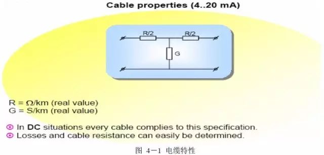
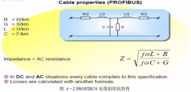
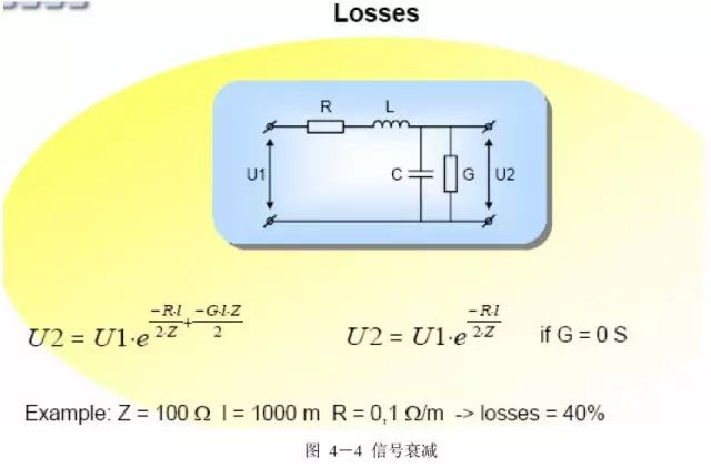
Ideally, due to the in-phase relationship between the voltage and current of the resistive components, the input signal experiences no phase shift when passing through the resistive network, only inherent attenuation. In practical circuits, since cables do not possess purely resistive characteristics but also have inductive characteristics (the voltage and current magnitude of inductive components are related not only to the inductance but also to the signal frequency. For a linear inductor, under a constant current, the voltage is proportional to the frequency. Therefore, in a DC circuit, where f=0, the inductor behaves like a short circuit.) and capacitive characteristics (the voltage and current magnitude of capacitive components are related not only to the capacitance but also to the signal frequency. For a linear capacitor, under constant voltage, the current is inversely proportional to the frequency. Therefore, in a DC circuit, where f=0, the capacitor behaves like an open circuit.), the characteristics of the cable cannot be simply described using resistive characteristics but must be described using impedance characteristics in relation to the input signal.
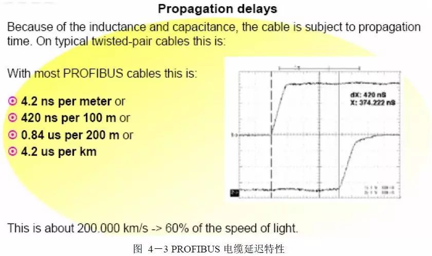
Due to the aforementioned impedance characteristics of the cable, the current or voltage signal experiences not only inherent amplitude attenuation after transmission through the cable but also inherent phase shift effects, i.e., delay characteristics.
2. Attenuation and Skin Effect
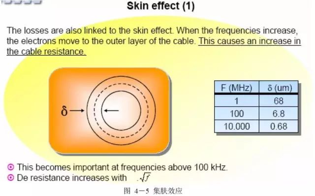
In high-frequency situations, the transmission current tends to concentrate on the surface of the conductor, thereby reducing the effective conductive area of the wire, which increases the resistance of the conductor and consequently increases the voltage drop across the conductor, leading to signal amplitude attenuation. The skin effect is proportional to the square root of the frequency.
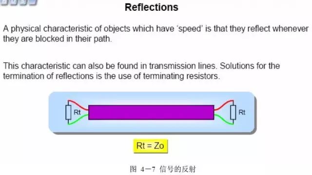
3. Signal Reflection
In physics, we know that for an object moving at a certain speed, if it encounters an obstruction during its motion, it will produce a reflection or rebound phenomenon. This property also applies to signals transmitted over cables, i.e., transmitted signals will produce reflection phenomena. The signal reflection phenomenon can be resolved by matching appropriate termination resistors at the cable’s ends.
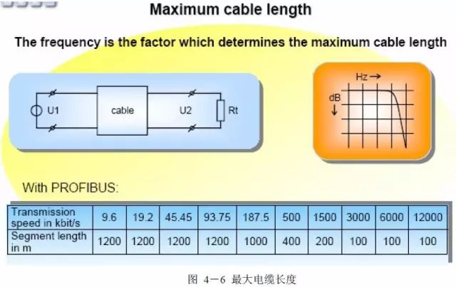
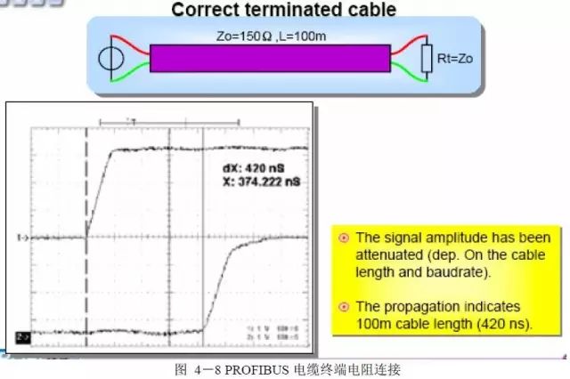
The degree of amplitude attenuation of the transmitted signal depends on the length of the cable and the transmission rate.
Every 100 meters of transmission cable causes a delay of 420ns to the transmitted signal.
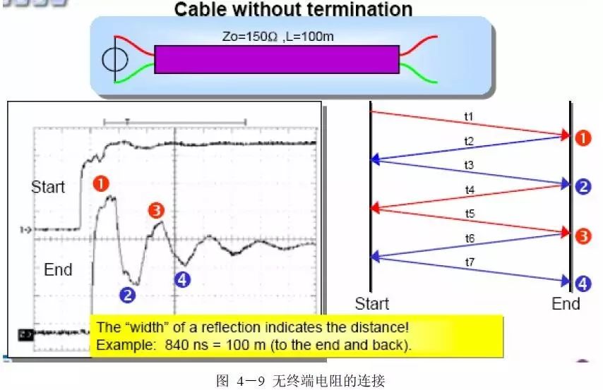
If the cable does not have a matching terminator, it will cause reflection of the transmitted signal, and the distance of reflection can be calculated from the width of the reflected wave.
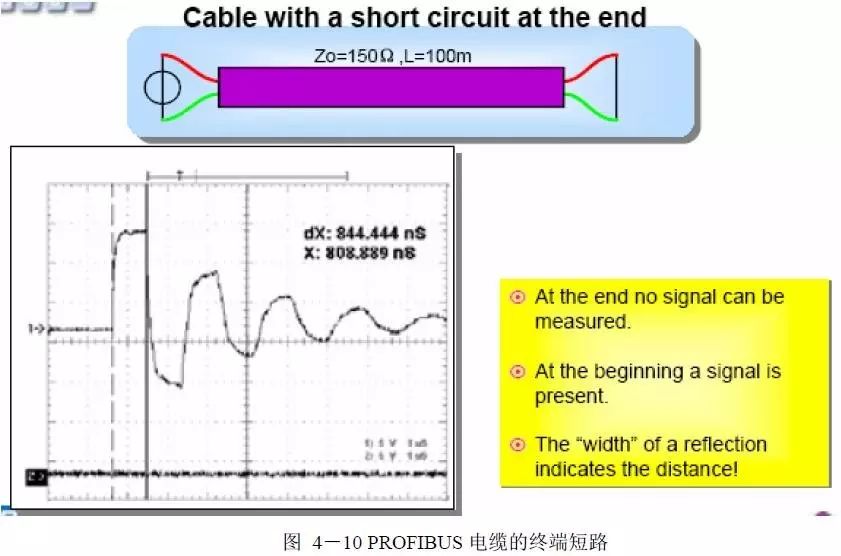
If a short circuit occurs between the two data lines of the transmission cable, it will also produce a reflection phenomenon. When the signal cannot be detected at the end of the cable, the distance of the short circuit can be determined from the width of the reflected wave.
5 Grounding and Shielding
In the PROFIBUS DP system, data transmission is based on an interference-resistant symmetrical bus system (using shielded twisted pair cables according to the RS485 specification). Due to proper system installation, some minor external interference sources are grounded through cable shielding without causing interference on the data lines. Using appropriate EMC measures, such as EMC-compliant system installation, EMC-compliant cable laying, and avoiding large grounding potential differences, can largely prevent this type of interference. At both ends of the cable, the cable shielding must be functionally connected to a large area grounding surface. Separating the PROFIBUS cable from interference sources and minimizing the length of any parallel extending cables can reduce interference.
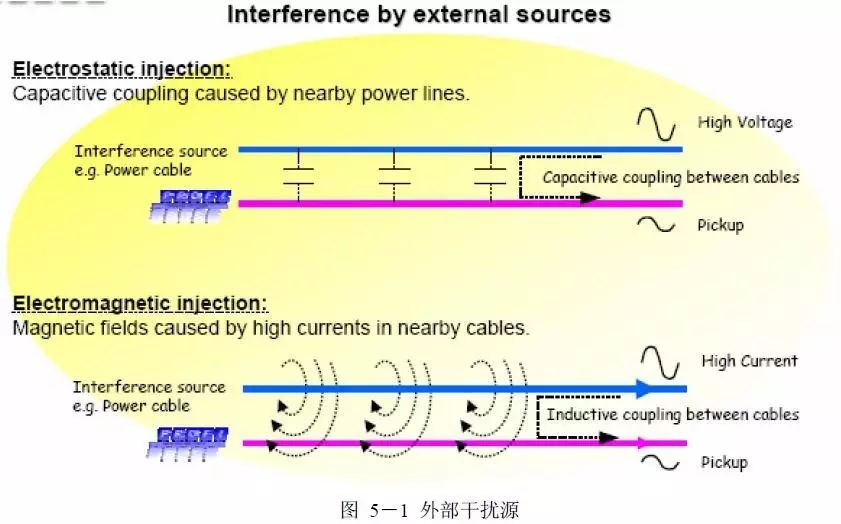
1. External Interference Sources
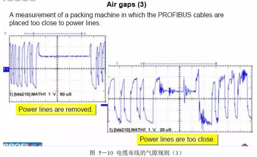
Generally, cable routes in workshops or factories may carry high voltage and large current. Laying PROFIBUS cables parallel to such cables can lead to interference, affecting normal communication and causing data transmission errors.
The coupling capacitance generated between high voltage cable routes and parallel laid PROFIBUS cables is a source of electrostatic interference. The axial electromagnetic field generated by large currents in the cable routes is a source of electromagnetic interference.
Functionally providing a zero voltage reference point for the equipment shielding, connecting the shielding layer of the PROFIBUS cable can effectively transfer electrostatic interference from the ground without causing interference in the device’s electronic circuits. In high-frequency circuits, the effects of parasitic capacitance and inductance are significant, and circuits with frequencies greater than 10MHz typically use multipoint grounding.
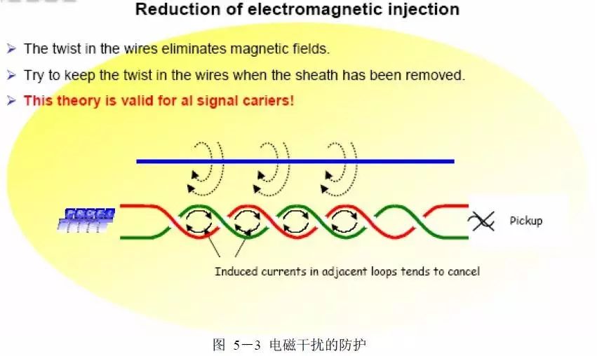
PROFIBUS uses RS 485 transmission technology and shielded twisted pair data cables to effectively eliminate electromagnetic interference.
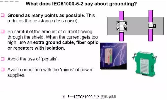
2. IEC 61000-5-2
● When using multipoint grounding, each ground wire can be very short; and multiple wires in parallel can reduce the total inductance of the grounding conductor.
● Attention should be paid to the magnitude of the current flowing through the shielding layer; when the current is large, additional grounding cables, fiber optic cables, or repeaters should be added for isolation.
● Avoid the “pig tail effect” at the shielding cable joints during shielding grounding.
● Avoid connections with “negative” power systems.
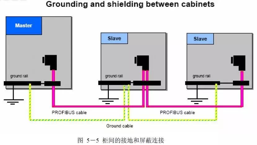
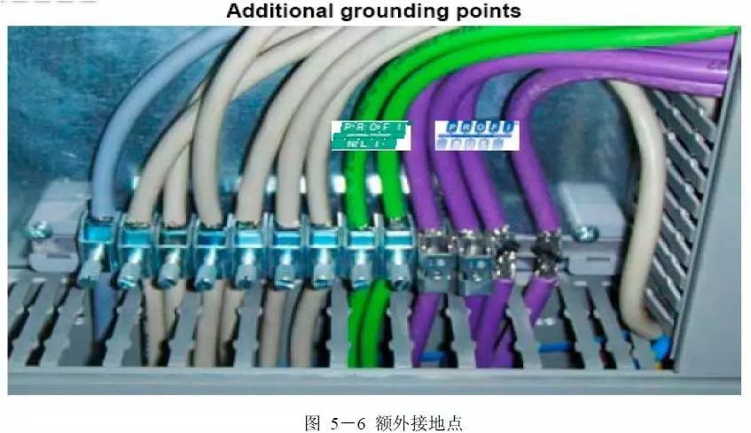
3. Grounding and Equipotential Connections of PROFIBUS Networks
Correct grounding ensures reduced electrostatic interference, thereby minimizing interference. Equipotential connections ensure that the ground or earth potential is equal throughout the network. This balances the ground potential of different cabinets in the workshop, preventing ground currents from flowing through the PROFIBUS cable shielding. Attention should be paid to the following points for equipotential connections:
● Connect to grounding rods or large area grounding terminals.
● Connect all PROFIBUS device shields and grounding connections to the equipotential grounding system.
● Place equipotential connections as close as possible to the laying of the PROFIBUS cable.
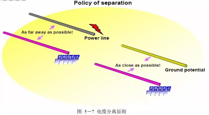
4. Distance Between PROFIBUS Cables and Power Cables
● The greater the distance between PROFIBUS cables and power cables, and the shorter the parallel running route, the lower the risk of interference.
● PROFIBUS cables should be laid parallel to and as close as possible to the equipotential connection cables.
● The shielding of PROFIBUS cables should be connected to the building’s grounding system as close as possible to the cable entry point.
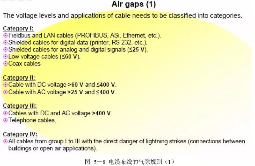
Based on voltage levels and application scenarios, cables can be categorized into the following four types:
Type 1:
● Fieldbus cables and network cables (PROFIBUS cables, ASi bus cables, Ethernet cables, etc.)
● Digital signal shielded cables (printer cables and RS232 cables)
● Analog and digital signal cables (≤25V)
● Low voltage cables (≤60V)
● Coaxial cables
Type 2:
● DC line cables (60V~400V)
● AC line cables (25V~400V)
Type 3:
● AC and DC line cables (>400V)
● Telephone line cables
Type 4:
● Cables of Types 1 to 3 installed outdoors
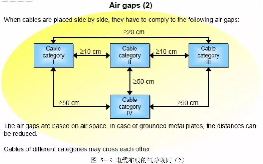
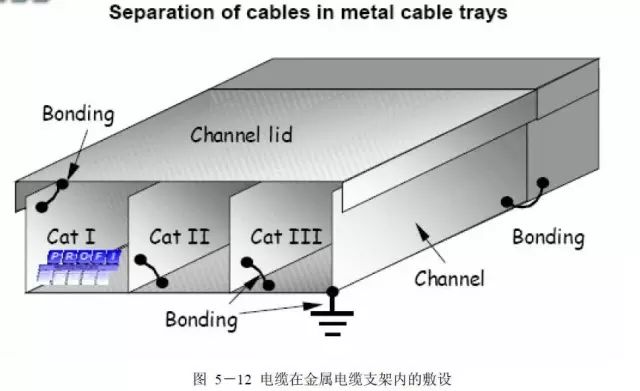
Different categories of cables must comply with the spacing rules shown in the figure when laid in parallel.
In addition to ensuring that different categories of cables are separated in the cable trays, attention must also be paid to:
● All parts of the metal cable trays should be connected to each other. For this, use dedicated connecting chains or jumpers, ensuring that the material used for the connecting chain is the same as that of the cable tray.
● Connect as many metal cable trays as possible to the equipotential connection system.
● For extended junction points, curved connecting chains can be used.