When mentioning Siemens’ communication, we must talk about PROFIBUS. Are you familiar with it? PROFIBUS is used in what ways?
PROFIBUS supports master-slave mode as well as multi-master and multi-slave operating modes. In a multi-master environment, the control of the bus is determined by a token-passing method among the masters; once control is obtained, the master can send and receive data with the slaves, achieving point-to-point communication.
The architecture of PROFIBUS
The PROFIBUS protocol mainly consists of three core components:PROFIBUS-DP (Decentralized Periphery), PROFIBUS-PA (Process Automation), and PROFIBUS-FMS (Fieldbus Message Specification).
1. PROFIBUS-DP (Decentralized Periphery)
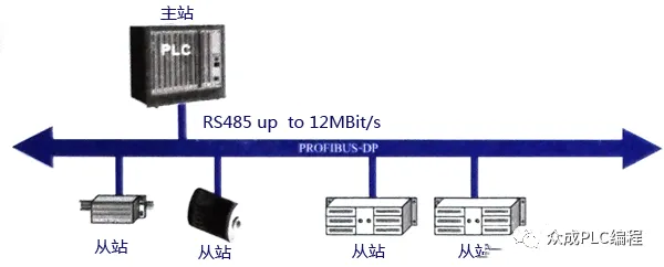
PROFIBUS-DP focuses on high-speed and cost-effective data transmission, suitable for communication between unit-level control devices and distributed I/O (such as ET 200) in automation systems. Communication between masters follows a token mechanism, while communication between masters and slaves is conducted through master-slave polling or a combination of both. In a typical PROFIBUS-DP network, there is one active token (master) and multiple passive nodes (slaves).
Figure 1 shows a typical master-slave PROFIBUS-DP bus structure, where one station acts as the master and the others are all slaves.
2. PROFIBUS-PA (Process Automation)
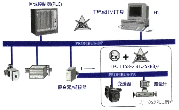
PROFIBUS-PA is used for low-speed data transmission of field sensors and actuators in process automation; it is based on the extended PROFIBUS-DP protocol. It uses IEC 1158-2 standard transmission technology, making it suitable for communication between explosion-proof area sensors and actuators and central control systems. It employs shielded twisted-pair cables and is powered by the bus. Figure 2 depicts a typical PROFIBUS-PA system configuration.
3. PROFIBUS-FMS (Fieldbus Message Specification)
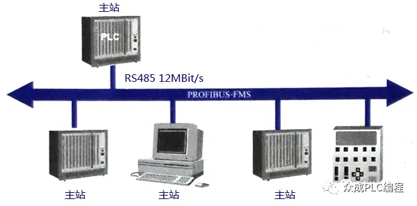
PROFIBUS-FMS serves workshop-level monitoring networks, providing a wide range of communication services and supporting cyclic and acyclic communication at medium speeds. FMS focuses on system functionality rather than system response time. As shown in Figure 3, a typical PROFIBUS-FMS system consists of various intelligent automation units, such as PC, PLC, HMI, etc.
The protocol hierarchy of PROFIBUS
The protocol structure of PROFIBUS is based on the ISO/OSI reference model, as shown in Figure 4. The first layer is responsible for physical transmission characteristics, the second layer involves the data link layer, while layers 3 to 6 are not used in PROFIBUS. The seventh layer is the application layer, defining application functions.
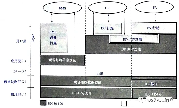
PROFIBUS-DP is known for its efficiency and speed, using only the first two layers and the user interface while omitting layers 3 to 7. This simplified structure ensures high-efficiency data transmission for DP.
Transmission Technology
PROFIBUS bus adopts a bus topology with terminals, as shown in Figure 5.
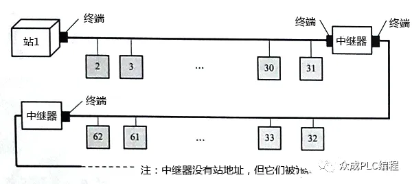
In terms of transmission technology, both PROFIBUS DP and PROFIBUS FMS use the same mechanism, which can employ RS485 shielded twisted-pair cables or fiber optics for transmission; while PROFIBUS PA uses IEC 1158-2 transmission technology. DP and FMS use a unified bus access protocol, allowing them to operate simultaneously on the same cable. They comply with the EIA RS-485 standard (also known as H2) and can use shielded or unshielded twisted-pair cables, operating within a speed range of 9.6kbit/s to 12Mbit/s. Without repeaters, a single bus segment can connect up to 32 stations, while with repeaters, it can reach up to 127 stations. The transmission distance of DP/FMS is related to the transmission rate, being 100m at 3-12Mbit/s and 1200m at 9.6-93.75kbit/s.
To adapt to high-intensity electromagnetic interference environments or achieve high-speed long-distance transmission, PROFIBUS also supports fiber optic transmission technology.
Application of PROFIBUS bus connectors
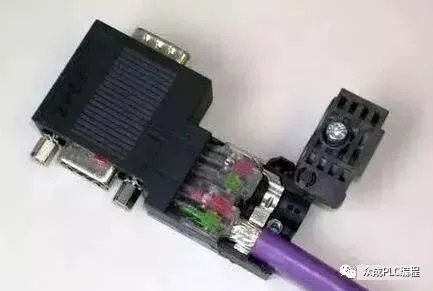
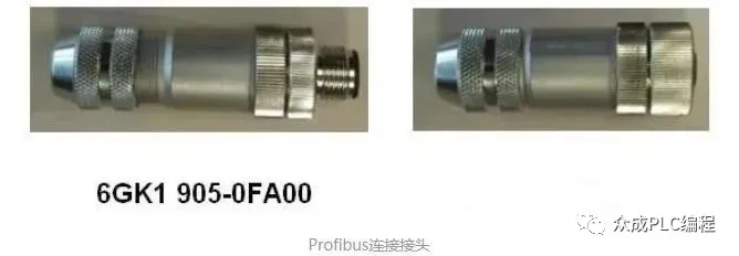
PROFIBUS bus connectors are designed to connect PROFIBUS sites with cables for efficient signal transmission. They are equipped with built-in terminal resistors, as shown in Figure 6, providing important assurance for the stable operation of the system.
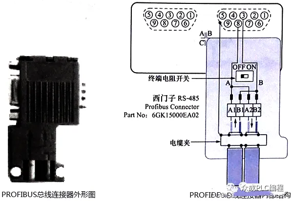
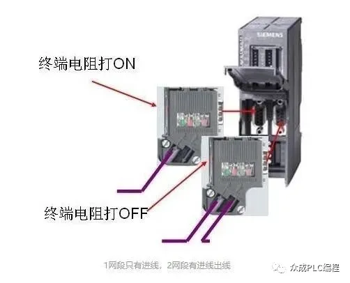
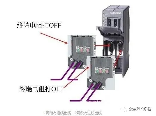
The standard wiring method for PROFIBUS-DP cables is illustrated in the figure, which is intuitive and easy to understand. This cable consists of two main conductors, one red and one green, with an outer shielding layer. During the wiring process, ensure that the shielding layer is correctly connected to avoid contact with the internal conductors. In addition, differentiate between incoming and outgoing wires, especially in bus systems, where a series connection is often used to continuously connect sub-stations through a single bus. At the joints at both ends of the bus, the cable should be connected to the incoming hole, and the switch should be set to the ON position, allowing only the incoming path to be open while the outgoing path is disconnected. The switch at the intermediate joints should be set to the OFF position to ensure that both incoming and outgoing lines are unobstructed.
PROFIBUS-DP wiring and procurement guide
Whether constructing an MPI or PROFIBUS-DP network, the main components required are similar. The specific models of cables and connectors can refer to common accessory order numbers. The following are the detailed steps:
A. Prepare cables and stripping tools. When using FC technology, there is no need to strip the exposed copper wire.

The above figure shows one end of the PROFIBUS cable stripped using a quick stripper (FCS, order number 6GK1905-6AA00).
B. Open the PROFIBUS network connector. First, release the cable tension clamp, then open the core wire lock.
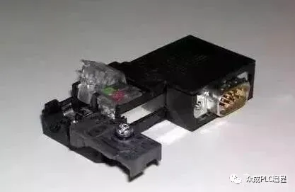
The above figure shows the opened PROFIBUS connector.
C. Remove the protective layer outside the cable core wire, insert the core wire into the core wire lock according to color markings, and press down the lock block firmly to ensure good contact of the internal conductors. At the same time, ensure that the stripped shielding layer of the cable contacts the shielding connection pressing piece.
The above figure shows the cable insertion process.
Due to the high communication frequency, the communication cable adopts a dual-end grounding method, ensuring that the shielding layers at both ends of the cable are connected.
D. Reset the cable clamp and tighten the screws to reduce the impact of external tension on internal connections.
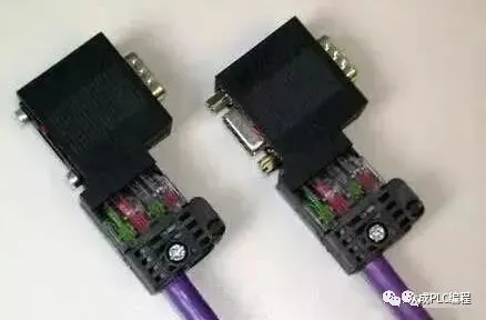
The network connector is divided into two types: with programming port and without programming port. The connector without programming port is suitable for general networking scenarios, while the connector with programming port can provide a programming connection port while networking, facilitating programming or connecting devices such as HMI.
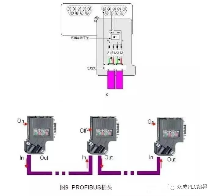
Connect the network plug through the PROFIBUS cable to construct a bus-type network structure. As shown in the figure below, connectors A, B, and C are connected to the communication ports of three communication sites; cable a connects plugs A and B, and cable b connects plugs B and C. This linear structure can be expanded as needed.
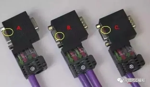
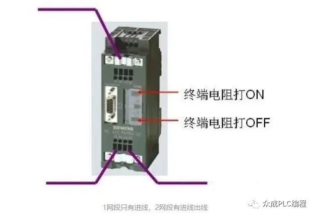
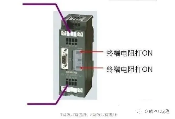
Pay attention to the setting of the “terminal resistor” switch in the circle. The plug at the network terminal must set the terminal resistor switch to the “ON” position; whereas the plug at the intermediate site should set the terminal resistor switch to the “OFF” position.
Precautions:
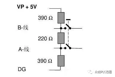
When the terminal resistor switch is set to “ON”, the device cannot be powered off. For example, the Profibus plug is equipped with two 390-ohm bias resistors in addition to the 220-ohm terminal resistor, and these bias resistors must be connected to the power supply.
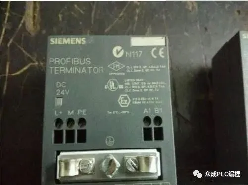
If terminal devices need frequent power outages for maintenance or are only equipped with terminal blocks without 9-pin D-type sockets, it is recommended to use active terminal modules as the terminals for the Profibus bus (e.g., 6ES7 972-0DA00-0AA0).
When the length of the Profibus cable is insufficient, use professional connectors to connect two cables, rather than simply twisting the copper cores together, to avoid damaging the characteristic impedance of the cable and causing communication problems.
The terminal resistor configuration of the RS485 repeater
The maximum length of the Profibus communication cable is limited by the communication baud rate. When the cable length exceeds the communication range, RS485 repeaters must be used to extend the communication distance. The repeater is equipped with terminal blocks, allowing direct connection of the Profibus cable. Additionally, the repeater is also equipped with terminal resistors, which are used in the same way as the cable plugs.
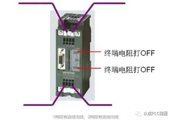
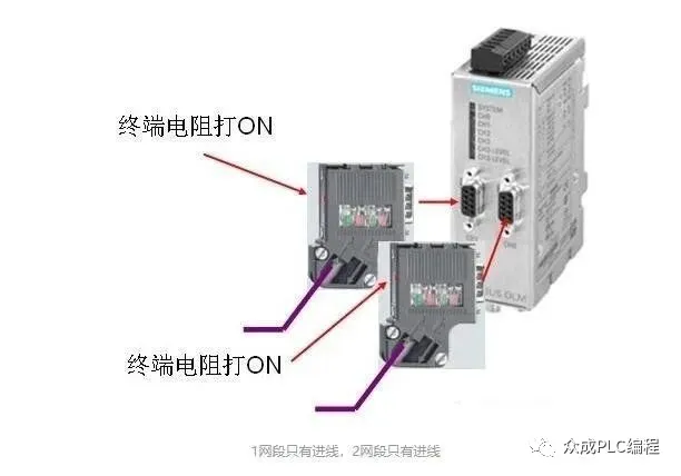
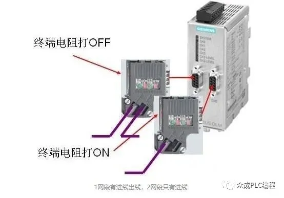
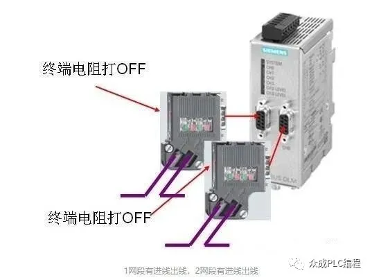
Application of OLM plug terminal resistors
In field environments with severe electromagnetic interference or long communication distances, OLM can be used to convert electrical signals into optical signals for transmission via optical fibers. OLM is equipped with RS485 electrical interfaces and needs to use Profibus plugs to connect cables. The connection method is the same whether connecting to a master or a slave.
Configuration of terminal resistors for DP/DP coupler plugs
Data can be transmitted between two DP masters via a DP/DP coupler. The DP/DP coupler is equipped with two RS485 interfaces, and the connection method is the same as that of OLM.

Although PROFIBUS-DP may seem unsafe in certain situations, mainly due to its high operational requirements, it can also demonstrate excellent stability as long as the specifications are followed and all work is carried out correctly. Despite the increasing preference for PROFINET, mastering PROFIBUS-DP still holds practical significance for many older devices.