Profibus Wiring
Whether forming an MPI or a PROFIBUS-DP network, the main components used are the same:
-
PROFIBUS cable: There are various cable models, among which the most basic is the PROFIBUS FC (Fast Connect) standard cable (order number 6XV1 830-0EH10).
-
PROFIBUS network connectors: There are also various forms of network connectors, such as different exit angles, etc.
Connecting Network Connectors
A. Cable and stripper. Using FC technology does not require stripping out exposed copper wire.

Figure 1. The stripped end of the PROFIBUS cable with a quick stripper (FCS, order number 6GK1905-6AA00).
B. Open the PROFIBUS network connector. First, open the cable tension release block, then lift the core wire lock.
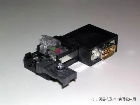 Figure 2. Opened PROFIBUS connector
C. Remove the protective layer outside the core wire of the PROFIBUS cable, insert the core wire into the core wire lock according to the corresponding color markings, and then press down the lock block firmly to make contact with the internal conductors. Note to ensure that the stripped shielding layer of the cable contacts the shielding connection pressure piece.
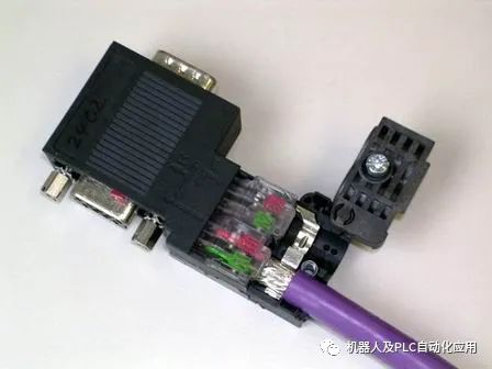 Figure 3. Inserting the cable
 Due to the high communication frequency, the communication cable uses dual-ended grounding. The shielding layer at both ends of the cable must be connected.
D. Reset the cable pressure block, tighten the screws, and eliminate the impact of external tension on the internal connection.
Network Connectors
Network connectors are mainly divided into two types: with and without programming ports. Connectors without programming ports are used for general networking, while connectors with programming ports can still provide a programming connection port while networking, used for programming or connecting to HMI, etc.
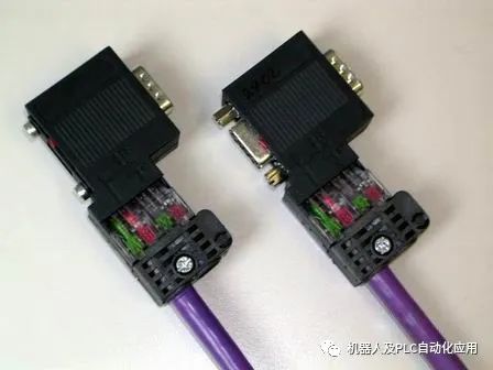 Figure 4. The left side is a network connector without a programming port (order number: 6ES7 972-0BA52-0XA0) and the right side is a network connector with a programming port (order number: 6ES7 972-0BB52-0XA0)
Linear Network Structure
Connect network plugs through PROFIBUS cables to form a bus-type network structure.
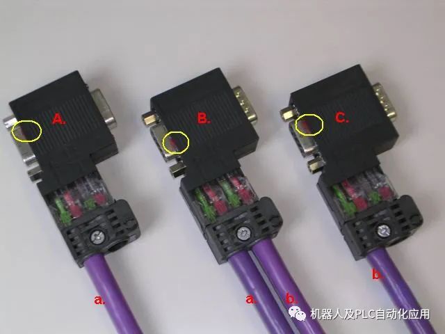 Figure 5. Bus-type network connection
In the above figure, network connectors A, B, and C are inserted into the communication ports of three communication stations; cable a connects plugs A and B, while cable b connects plugs B and C. The linear structure can be expanded accordingly.
Note the switch settings for the “termination resistor” in the circle. The plug at the end of the network must have its termination resistor switch set to “ON”; the plug at the intermediate station should have its termination resistor switch set to “OFF”.