5 Methods for Switching RS-485 Direction and Their Advantages and Disadvantages Analysis (ClickRead)
[Guide] Hello everyone, I am Yijun. In the previous article, I summarized the industrial HART bus. Today, let’s talk about the RS-485 bus. RS-485 is also a widely used communication interface. This article will discuss the key points, and it may be a bit long, about 5000 words.
The Past and Present
-
Industrial HART Bus -
Modbus Protocol -
Profibus DP -
…….
Electrical Characteristics
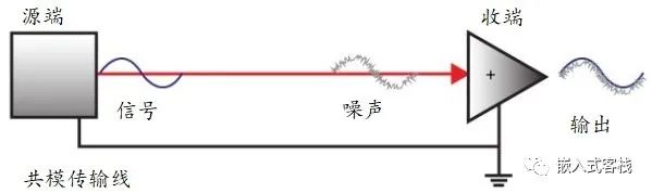
Common Mode Transmission
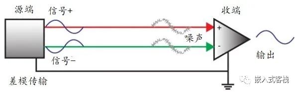
Differential Mode Transmission
Electrical Parameters
-
Common mode voltage range: -7 to +12V -
Supports up to 32 multipoint topology connections, see the network topology diagram below -
When using a 40-foot cable, the transmission rate can reach 10Mbps, where 1 foot equals 30.48cm, and Mbps means megabits/s -
When using a 4000-foot cable, the transmission rate can reach 100kbps -
Half-duplex communication -
Minimum differential voltage tolerance: 200mV, meaning that the receiving end cannot correctly identify 0/1 when the differential voltage is below 200mV. How should this be understood?
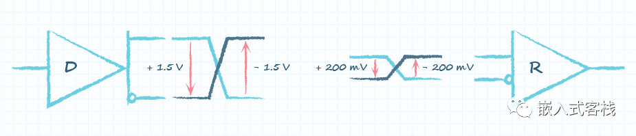
: The receiving circuit determines the difference between the common mode voltage of line A and line B:
If , then the receiving circuit R recognizes it as logic 1 If , then the receiving circuit R recognizes it as logic 0 In simple terms, if the absolute voltage value of line A is at least 200mV greater than that of line B, it is recognized as logic 1; or if the absolute voltage value of line A is at least 200mV less than that of line B, it is recognized as logic 0

-
RS-485 communication from the perspective of microcontroller/DSP/processor interface uses the UART interface with the RS-485 transceiver interface. Of course, you might ask if it is possible to use FPGA? Certainly, it is possible to implement a serial transceiver IP module using FPGA. You might even say that simulating UART with GPIO is also feasible, but it is not very meaningful as it requires CPU resources to implement the low-level BIT transmission. -
As mentioned earlier, half-duplex implies that there is full-duplex. What is half-duplex? First, half-duplex and full-duplex refer to point-to-point communication. Here, point-to-point means at the same time, where half-duplex means that the device is either in receiving data mode or in sending data mode at the same time and does not allow simultaneous send/receive data. Full-duplex, on the other hand, allows simultaneous send/receive. For example, the I2C bus is a half-duplex bus, while a 4-wire SPI is full-duplex, and a 3-wire SPI is a half-duplex bus; RS-422 or RS-232 are full-duplex interfaces; and CAN bus is a half-duplex bus. RS-485 is a half-duplex bus:
-
When the Host sends data, the data travels along the red line through the twisted pair to the Slave’s differential receiving circuit. When the Slave responds, data travels in the blue direction to the Host’s receiving circuit. However, since the transmission medium is a pair of twisted wires, one party cannot transmit signals while the other is transmitting data. From the transceiver’s control perspective: On the control chip side, a GPIO pin is used to control the transceiving enable, and a block diagram of the internal principle of the chip makes it easy to understand:

-
When DIR=0, the receiving circuit is enabled, and the sending circuit is disabled (DE=0), which is equivalent to high impedance for the bus. When DIR=1, the receiving circuit is enabled, and the sending circuit is disabled (DE=1), which depends on the DI signal for bus A/B signals. Here are two questions: 1. Why does the chip design the to have opposite effective logic? This is actually convenient for controlling the sending and receiving circuits with one GPIO. 2. Why not make the transceiver chip’s transceiving enable a single pin? For example, just call it DIR? It could be made into two pins for send/receive, allowing for separate control, such as : 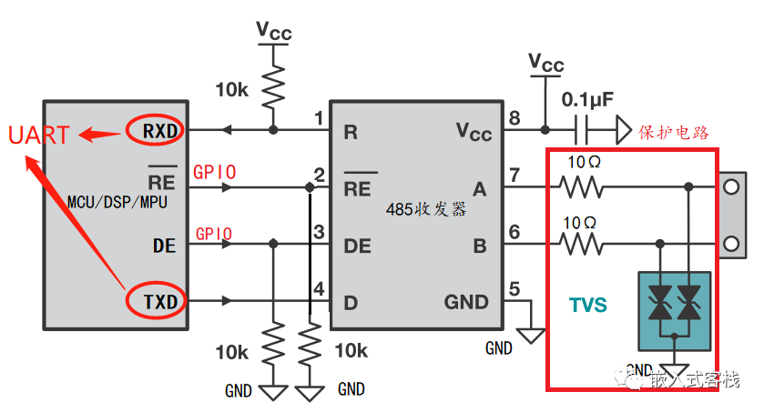
-
It is even possible to set DE=1 to 0 when DE=1, which would enable self-looping. This design can allow for self-diagnosis of the transceiver and wiring by comparing received messages with sent messages, allowing diagnosis of chip soldering, transceiver damage, or open circuits, as well as short circuit faults in wiring. However, you might say this is nonsense! You previously said RS-485 cannot send and receive simultaneously, but here you say it can! Isn’t that contradictory? No, it is not contradictory. What was previously mentioned about not being able to send and receive simultaneously refers to not being able to receive messages from other devices while sending; here, receiving refers to the messages sent by itself. Therefore, the essence of half-duplex is that the communication medium does not have a bidirectional channel. When sending data to the bus, the medium is occupied, and even if it wants to send, it cannot correctly send the signal to the medium. If forced to send, the data will be disordered, and the transceiver chip may even be damaged. -
: Receiver Output Enable, receiver enable, -
DE: Driver Output Enable, driver output enable -
The DIR pin in the diagram controls whether the current RS-485 is in