
PLC, inverters, and human-machine interfaces are important devices in modern industrial automation control. The application of these devices makes the production and manufacturing processes in factories more automated, efficient, precise, and controllable, significantly promoting the automation process of China’s manufacturing industry and making a huge contribution to the country’s modernization efforts.
The touch screen is a digital input-output device with touch display functionality, also known as a human-machine interface (HMI). When the touch screen is connected to the PLC, it can not only operate the PLC but also monitor the working status of some internal soft components of the PLC in real-time. To use the touch screen for operating and monitoring the PLC, a special configuration software must be used on the computer to create (also known as configuration) the corresponding operation and monitoring screen items for the touch screen, and then download the screen items to the touch screen.
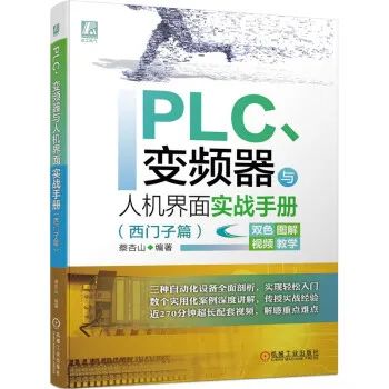
Today, I would like to introduce a book titled Practical Handbook for PLC, Inverters, and HMI (Siemens Edition). This book introduces Siemens PLC, inverter, and human-machine interface configuration technology. The main contents include the basics of PLC and practical entry into Siemens PLC, introduction to Siemens S7-200 SMART PLC, usage of S7-200 SMART PLC programming software, usage and examples of basic instructions, usage and examples of sequential control instructions, usage and examples of functional instructions, PLC communication, usage of Siemens inverters, inverter application circuits, comprehensive application of PLC and inverters, introduction to Siemens touch screens, quick start for Siemens WinCC configuration software, usage of common objects in WinCC software, and practical operation of PLC controlled by Siemens touch screens.
Click the image to purchase
Book Features
◆ Low starting point. Readers only need to have a junior high school education level to read.◆ Simple and understandable language. The book uses few specialized terms, and when encountering difficult content, it uses vivid metaphors to explain, avoiding complex theoretical analysis and cumbersome formula derivations, making the reading feel very smooth.◆ Detailed content explanation. Considering that there is generally no guidance during self-study, the knowledge and skills in the book are explained in detail during the writing process, allowing readers to easily understand the content they have learned. At the same time, relevant key content teaching videos are provided in the book, which can be watched by scanning the QR code to further deepen understanding.◆ Rich in illustrations. The book uses a large number of intuitive and visual charts that readers like to present content, making reading very easy and reducing reading fatigue.◆ Content arrangement follows cognitive rules. This book determines the order of chapters based on the principle of gradual progression from easy to difficult, allowing readers to read the book from front to back naturally.◆ Key knowledge points are highlighted. To help readers grasp the key knowledge points in the book, the book highlights key knowledge points using shading and bold text to indicate learning focus.◆ Free online tutoring. If readers encounter difficult-to-understand questions while reading, they can add the Yitian Electrical Network WeChat public account etv100 to request relevant learning materials or ask teachers questions for learning.
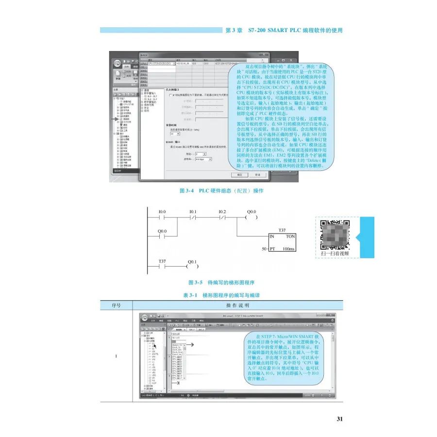
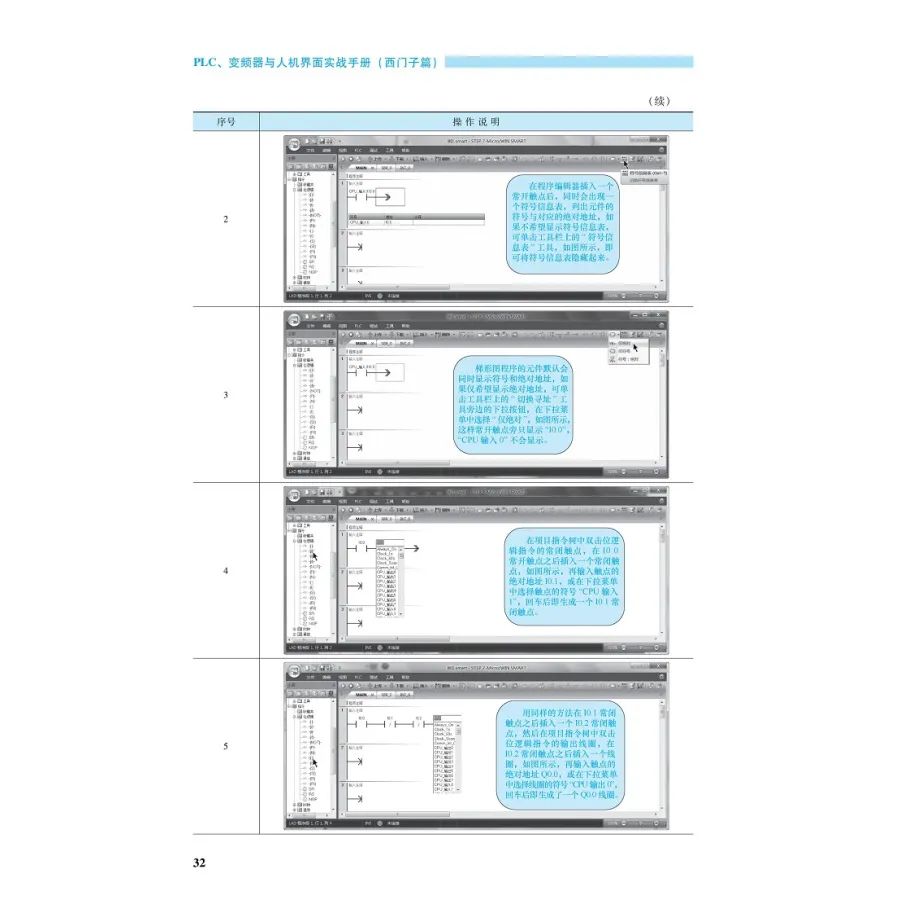
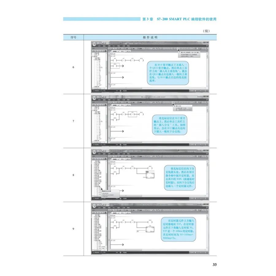
Drag the scrollbar on the right to view the full directory▼Directory
Foreword
Chapter 1 PLC Basics and Practical Entry into Siemens PLC 1
1.1 PLC and PLC Control 1
1.1.1 What is PLC 1
1.1.2 Comparison of PLC Control and Relay Control 2
1.2 Types and Characteristics of PLC 3
1.2.1 Types of PLC 3
1.2.2 Characteristics of PLC 4
1.3 Composition and Working Principle of PLC 4
1.3.1 Schematic Diagram of PLC Composition 4
1.3.2 CPU and Memory 5
1.3.3 Input Interface Circuit 6
1.3.4 Output Interface Circuit 6
1.3.5 Communication Interface, Expansion Interface, and Power Supply 7
1.3.6 PLC Working Modes 7
1.3.7 Example of PLC Control Circuit’s Software and Hardware Working Process 8
1.4 PLC Programming Languages 9
1.4.1 Ladder Diagram 9
1.4.2 Function Block Diagram 10
1.4.3 Instruction Statement Table 10
1.5 Development Example of Siemens PLC Controlling Dual Lamps 10
1.5.1 General Process of PLC Application System Development 10
1.5.2 System Control Requirements 11
1.5.3 Selecting PLC Model and Determining Input/Output Devices and I/O Terminals 11
1.5.4 Drawing the Circuit Diagram for PLC Controlling Dual Lamps (See Figure 1-16) 11
1.5.5 Writing PLC Program with Programming Software 11
1.5.6 DC24V Power Adapter and Power Cable 12
1.5.7 Connecting Computer and PLC with Programming Cable 14
1.5.8 Downloading Program to PLC 14
1.5.9 Simulation Debugging 15
1.5.10 Actual Wiring 15
1.5.11 Actual Operation Testing 16
Chapter 2 Introduction to Siemens S7-200 SMART PLC 17
2.1 Introduction to PLC Hardware 17
2.1.1 Two Types of CPU Modules 17
2.1.2 Explanation of Each Component of the CPU Module Panel 18
2.1.3 Wiring of CPU Module 18
2.1.4 Installation and Usage of Signal Board and Address Allocation 20
2.1.5 Common Modules and Order Numbers of S7-200 SMART PLC 23
2.2 Soft Components of PLC 25
2.2.1 Input Relays and Output Relays 25
2.2.2 Auxiliary Relays, Special Auxiliary Relays, and Status Relays 26
2.2.3 Timers, Counters, and High-Speed Counters 26
2.2.4 Accumulators, Variable Memory, and Local Variable Memory 27
2.2.5 Analog Input Registers and Analog Output Registers 27
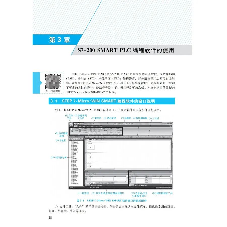
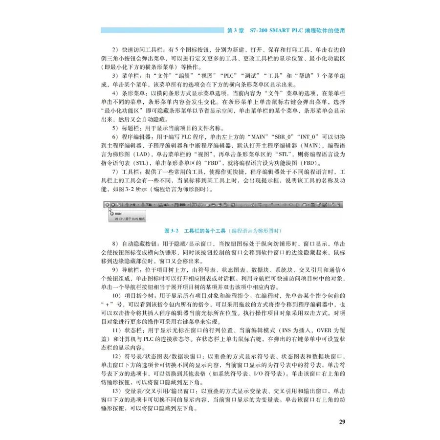
Chapter 3 Usage of S7-200 SMART PLC Programming Software 28
3.1 Explanation of STEP7-Micro/WIN SMART Programming Software Window 28
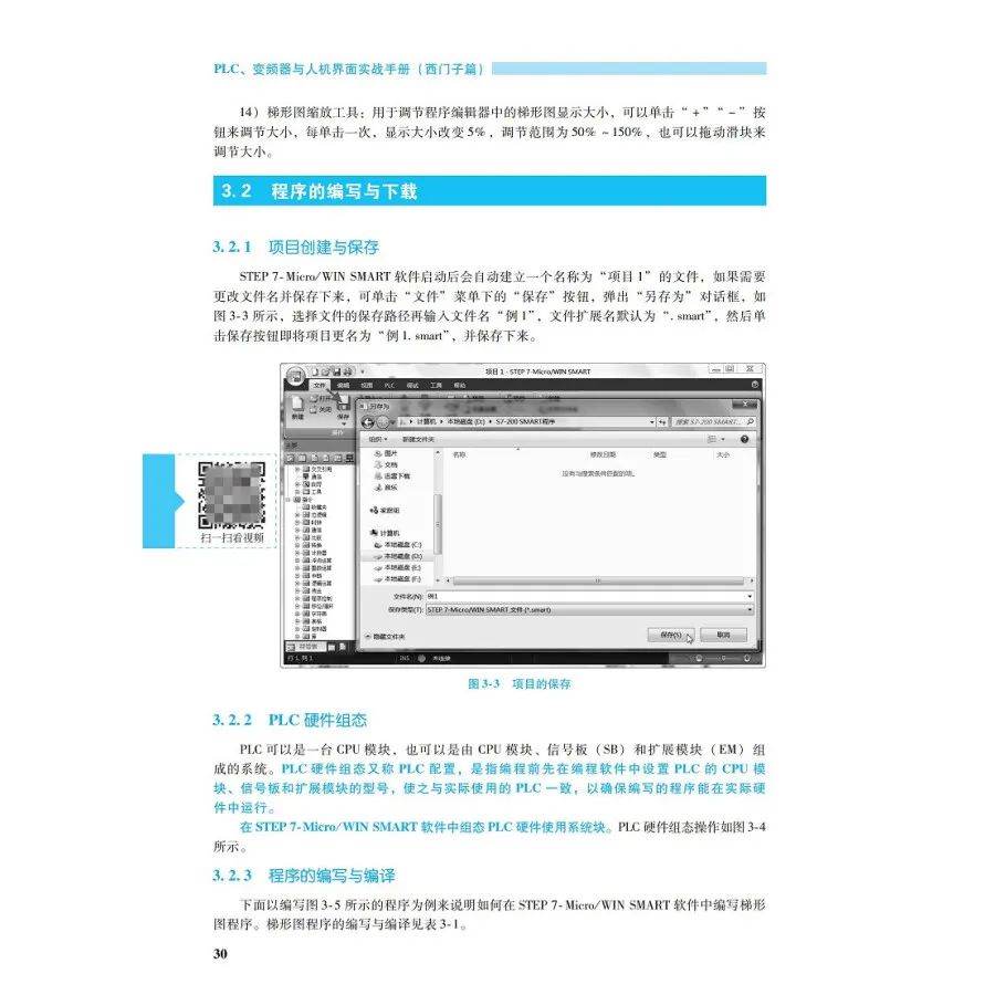
3.2 Writing and Downloading Programs 30
3.2.1 Creating and Saving Projects 30
3.2.2 PLC Hardware Configuration 30
3.2.3 Writing and Compiling Programs 30
3.2.4 Connection and Communication Settings between PLC and Computer 34
3.3 Editing and Commenting Programs 39
3.3.1 Editing Programs 39
3.3.2 Commenting Programs 42
3.4 Monitoring and Debugging Programs 44
3.4.1 Monitoring and Debugging Programs Using Ladder Diagrams 44
3.4.2 Monitoring and Debugging Programs Using State Chart Tables and Trend Graphs 47
3.4.3 Monitoring and Debugging Programs Using State Chart Trend Graphs 49
3.5 Object Settings, Hardware Configuration, and Data Copying 50
3.5.1 Settings for Common Objects 50
3.5.2 Hardware Configuration 50
3.5.3 Backing Up, Copying Programs, and Refreshing Firmware Using Memory Cards 52
Chapter 4 Usage and Examples of Basic Instructions 56
4.1 Bit Logic Instructions 56
4.1.1 Contact Instructions 56
4.1.2 Coil Instructions 57
4.1.3 Immediate Instructions 58
4.1.4 RS Trigger Instructions 59
4.1.5 No Operation Instructions 60
4.2 Timers 60 4.2.1 On Delay Timer 61
4.2.2 Off Delay Timer 62
4.2.3 Memory On Delay Timer 63
4.3 Counters 64
4.3.1 Up Counters 64
4.3.2 Down Counters 65
4.3.3 Up/Down Counters 66
4.4 Common Basic Control Circuits and Ladder Diagrams 67
4.4.1 Start, Self-locking, and Stop Control Circuits and Ladder Diagrams 67
4.4.2 Forward and Reverse Interlocking Control Circuits and Ladder Diagrams 67
4.4.3 Multi-location Control Circuits and Ladder Diagrams 70
4.4.4 Timed Control Circuits and Ladder Diagrams 71
4.4.5 Long-time Timed Control Circuits and Ladder Diagrams 74
4.4.6 Multiple Output Control Circuits and Ladder Diagrams 75
4.4.7 Overload Alarm Control Circuits and Ladder Diagrams 76
4.4.8 Flashing Control Circuits and Ladder Diagrams 78
4.5 Siemens PLC Control Example for Fountains 79
4.5.1 System Control Requirements 79
4.5.2 I/O Terminals and Input/Output Devices 79
4.5.3 PLC Control Circuit 79
4.5.4 PLC Control Program and Detailed Explanation 79
4.6 Siemens PLC Control Example for Traffic Lights 82
4.6.1 System Control Requirements 82
4.6.2 I/O Terminals and Input/Output Devices 82
4.6.3 PLC Control Circuit 83
4.6.4 PLC Control Program and Detailed Explanation 84
4.7 Siemens PLC Control Example for Multi-level Conveyors 86
4.7.1 System Control Requirements 86
4.7.2 I/O Terminals and Input/Output Devices 86
4.7.3 PLC Control Circuit 86
4.7.4 PLC Control Program and Detailed Explanation 86
4.8 Siemens PLC Control Example for Automatic Garage Doors 89
4.8.1 System Control Requirements 89
4.8.2 I/O Terminals and Input/Output Devices 89
4.8.3 PLC Control Circuit 89
4.8.4 PLC Control Program and Detailed Explanation 89
Chapter 5 Usage and Examples of Sequential Control Instructions 92
5.1 Sequential Control and State Transition Diagrams 92
5.2 Sequential Control Instructions 93
5.2.1 Instruction Names and Functions 93
5.2.2 Examples of Instruction Usage 93 5.2.3 Notes on Instruction Usage 93
5.3 Several Methods of Sequential Control 95
5.3.1 Selective Branching Method 95
5.3.2 Parallel Branching Method 95
5.4 Siemens PLC Control Example for Liquid Mixing Devices 100
5.4.1 System Control Requirements 100
5.4.2 I/O Terminals and Input/Output Devices 100
5.4.3 PLC Control Circuit 100
5.4.4 PLC Control Program and Detailed Explanation 101
5.5 Siemens PLC Control Example for Simple Mechanical Arms 104
5.5.1 System Control Requirements 104
5.5.2 I/O Terminals and Input/Output Devices 104
5.5.3 PLC Control Circuit 104
5.5.4 PLC Control Program and Detailed Explanation 105
5.6 Siemens PLC Control Example for Sorting Machines for Large and Small Balls 108
5.6.1 System Control Requirements 108
5.6.2 I/O Terminals and Input/Output Devices 108
5.6.3 PLC Control Circuit 109
5.6.4 PLC Control Program and Detailed Explanation 109
Chapter 6 Usage and Examples of Functional Instructions 113
6.1 Data Types 113
6.1.1 Word Length 113
6.1.2 Data Types and Ranges 113
6.1.3 Programming Writing Format for Constants 114
6.2 Transfer Instructions 114
6.2.1 Single Data Transfer Instructions 114
6.2.2 Byte Immediate Transfer Instructions 115
6.2.3 Data Block Transfer Instructions 116
6.2.4 Byte Exchange Instructions 117
6.3 Comparison Instructions 117
6.3.1 Byte Contact Comparison Instructions 117
6.3.2 Integer Contact Comparison Instructions 118
6.3.3 Double Word Integer Contact Comparison Instructions 119
6.3.4 Real Number Contact Comparison Instructions 120
6.3.5 Examples of Comparison Instruction Applications 120
6.4 Arithmetic Operation Instructions 121
6.4.1 Addition, Subtraction, Multiplication, and Division Operation Instructions 121
6.4.2 Floating Point Function Operation Instructions 126
6.5 Logic Operation Instructions 127
6.5.1 Inversion Instructions 127
6.5.2 AND Instructions 128
6.5.3 OR Instructions 129
6.5.4 XOR Instructions 130
6.6 Shift and Loop Instructions 131
6.6.1 Left and Right Shift Instructions 131
6.6.2 Circular Left and Right Shift Instructions 132
6.7 Conversion Instructions 134
6.7.1 Standard Conversion Instructions 134
6.7.2 ASCII Code Conversion Instructions 136
6.8 Table Instructions 139
6.8.1 Fill Table Instructions 139
6.8.2 Lookup Table Instructions 140
6.9 Clock Instructions 141
6.9.1 Explanation of Clock Instructions 141
6.9.2 Examples of Clock Instruction Usage 142
6.10 Program Control Instructions 143
6.10.1 Jump and Label Instructions 143
6.10.2 Loop Instructions 144
6.10.3 End, Stop, and Monitor Timer Reset Instructions 145
6.11 Subroutines and Subroutine Instructions 146
6.11.1 Subroutines 146
6.11.2 Subroutine Instructions 147
6.12 Interrupt Events and Interrupt Instructions 149
6.12.1 Interrupt Events and Interrupt Priorities 149
6.12.2 Interrupt Instructions 152
Chapter 7 PLC Communication 155
7.1 Basic Knowledge of Communication 155
7.1.1 Communication Methods 155
7.1.2 Communication Transmission Media 157
7.2 PLC Ethernet Communication 158
7.2.1 Types of Devices Connected to S7-200 SMART PLC CPU Module via Ethernet 158
7.2.2 IP Address Settings 159
7.2.3 Ethernet Communication Instructions 163
7.2.4 PLC Ethernet Communication Examples 166
7.3 PLC’s RS-485/RS-232 Communication 170
7.3.1 RS-232C, RS-422A, and RS-485 Interface Circuit Structure 170
7.3.2 RS-485/RS-232 Pin Function Definitions 171
7.3.3 Getting Port Address Instructions and Setting Port Address Instructions 172
7.3.4 Sending and Receiving Instructions 173
Chapter 8 Usage of Siemens Inverters 179
8.1 Basic Structure and Principles of Inverters 179
8.1.1 Two Speed Control Methods for Asynchronous Motors 179
8.1.2 Structure and Principles of Two Types of Inverters 179
8.2 Structure and Wiring of Siemens MM440 Inverter 181
8.2.1 Appearance and Model (Order Number) Meanings 181
8.2.2 Internal Structure and External Wiring Diagram 182
8.2.3 External Terminal Wiring of Main Circuit 182
8.2.4 Typical Actual Wiring of Control Circuit External Terminals 185
8.2.5 Wiring and Parameter Settings of Digital Input Terminals 185
8.2.6 Wiring and Parameter Settings of Analog Input Terminals 186
8.2.7 Wiring and Parameter Settings of Digital Output Terminals 189
8.2.8 Wiring and Parameter Settings of Analog Output Terminals 189
8.3 Stopping, Braking, and Restarting Methods of Inverters 190
8.3.1 Motor Nameplate Data and Corresponding Inverter Parameters 190
8.3.2 Stopping Methods of Inverters 191
8.3.3 Braking Methods of Inverters 192
8.3.4 Restarting Methods of Inverters 193
8.4 Debugging Inverters Using Panels and External Terminals 193
8.4.1 Debugging Inverters Using SDP and External Terminals 194
8.4.2 Debugging Inverters Using BOP 194
8.4.3 Debugging Inverters Using AOP 197
8.5 Parameter Debugging and Routine Operations of MM440 Inverters 198
8.5.1 Resetting All Parameters of Inverters 198
8.5.2 Steps and Explanations for Quick Parameter Debugging Settings of Inverters 199
8.5.3 Routine Operations of Inverters 202
Chapter 9 Inverter Application Circuits 203
9.1 Inverter Circuit for Controlling Forward and Reverse Rotation with Input Terminals and Panel Keyboard Speed Regulation 203
9.1.1 Control Requirements 203
9.1.2 Circuit and Operation Instructions 203
9.1.3 Parameter Settings 204
9.2 Inverter Circuit for Controlling Forward and Reverse Rotation with Input Terminals and Panel Potentiometer Speed Regulation 204
9.2.1 Control Requirements 204
9.2.2 Circuit and Operation Instructions 205
9.2.3 Parameter Settings 205
9.3 Multi-speed Control and Application Circuits of Inverters 206
9.3.1 Three Methods for Multi-speed Control of Inverters 206
9.3.2 Application Circuits for Multi-speed Control of Inverters 207
9.4 PID Control Circuit of Inverters 209
9.4.1 Principles of PID Control 209
9.4.2 Parameters Related to PID 210
9.4.3 PID Control Inverter Circuit and Parameter Settings for Constant Pressure Water Supply 210
Chapter 10 Comprehensive Application of PLC and Inverters 214
10.1 PLC Control Circuit for Inverter Driving Motor with Delayed Forward and Reverse Rotation 214
10.1.1 Control Requirements 214
10.1.2 Distribution of PLC Input and Output Terminals 214
10.1.3 Circuit Wiring 214
10.1.4 Inverter Parameter Settings 214
10.1.5 PLC Control Program and Explanation 216
10.2 PLC Control Circuit for Realizing Multi-speed Operation of Inverters 217
10.2.1 Control Requirements 217
10.2.2 Distribution of PLC Input and Output Terminals 217
10.2.3 Circuit Wiring 217
10.2.4 Inverter Parameter Settings 217
10.2.5 PLC Control Program and Explanation 218
10.3 Application Example of PLC Controlling Inverter via USS Protocol Communication 219
10.3.1 Hardware Connection for S7-200 PLC and MM440 Inverter Serial Communication 219
10.3.2 USS Protocol 220
10.3.3 Installing USS Communication Library in S7-200 PLC Programming Software 222
10.3.4 USS Communication Instructions 223
10.3.5 Application Example of S7-200 PLC Controlling MM440 Inverter via USS Protocol Communication 229
Chapter 11 Introduction to Siemens Touch Screens 232
11.1 Basic Knowledge of Touch Screens 232
11.1.1 Basic Components 232
11.1.2 Working Principles 232
11.2 Introduction to Siemens Wonderful Series Touch Screens 234
11.2.1 Features of SMARTLINE Touch Screens 234
11.2.2 Common Models and Shapes 234
11.2.3 Explanation of Main Components of Touch Screens 235
11.2.4 Technical Specifications 236
11.3 Connection of Touch Screens with Other Devices 237
11.3.1 Power Wiring of Touch Screens 237
11.3.2 Ethernet Connection between Touch Screens and Configuration Computers 237
11.3.3 Connection between Touch Screens and Siemens PLCs 237
11.3.4 Connection between Touch Screens and Mitsubishi, Schneider, and Omron PLCs 238
Chapter 12 Quick Start for Siemens WinCC Configuration Software 241
12.1 Installation of WinCC flexible SMART V3 Software 241
12.1.1 System Requirements 241
12.1.2 Downloading and Installing Software 242
12.2 Configuring a Simple Project with WinCC Software 242
12.2.1 Creating and Saving Projects 242 12.2.2 Configuring Variables 244
12.2.3 Configuring Screens 246
12.2.4 Simulated Running of Projects 250
Chapter 13 Usage of Common Objects in WinCC Software 251
13.1 Examples of Using IO Domains 251
13.1.1 Configuring Tasks 251
13.1.2 Configuring Processes 251
13.1.3 Running Tests 253
13.2 Examples of Using Buttons 254
13.2.1 Configuring Tasks 254
13.2.2 Configuring Processes 255
13.2.3 Running Tests 257
13.3 Examples of Using Variable Control Object Animations 258
13.3.1 Configuring Tasks 258
13.3.2 Configuring Processes 259
13.3.3 Running Tests 261
13.3.4 Simulation Debugging 261
13.4 Examples of Using Pointer Variables 263
13.4.1 Configuring Tasks 263
13.4.2 Configuring Processes 263
13.4.3 Running Tests 266
13.5 Examples of Using Switches and Drawing Tools 267
13.5.1 Configuring Tasks 267
13.5.2 Configuring Processes 268
13.5.3 Running Tests 271
13.6 Examples of Using Alarm Functions 271
13.6.1 Basic Knowledge of Alarms 271
13.6.2 Configuring Tasks 273
13.6.3 Configuring Processes 273
13.6.4 Running Tests 277
13.7 Examples of Using Bar Graphs and Trend Graphs 279
13.7.1 Configuring Tasks 279
13.7.2 Configuring Processes 279
13.7.3 Running Tests 283
13.8 Examples of Using Screen Switching 284
13.8.1 Creating Screens (See Table 13-10) 284
13.8.2 Setting Screen Switching Functions Using Drag-and-Drop Button Methods 285
13.8.3 Using Buttons with Screen Switching Functions to Achieve Specified Screen Switching (See Table 13-11) 285
13.8.4 Using Buttons with Screen Switching Functions to Achieve Any Numbered Screen Switching 286
Chapter 14 Practical Operation of Siemens Touch Screens Controlling PLC 288
14.1 Clarifying Requirements, Planning Variables, and Circuits 288
14.1.1 Control Requirements 288
14.1.2 Selecting PLC and Touch Screen Models and Allocating Variables 288
14.1.3 Device Connection and Circuit 289
14.2 Writing and Downloading PLC Programs 289
14.2.1 Writing PLC Programs 289
14.2.2 Connection and Settings between PLC and Computer 290
14.2.3 Downloading and Uploading PLC Programs 291
14.3 Configuring and Downloading Touch Screen Screen Projects 293
14.3.1 Creating Touch Screen Screen Project Files 293
14.3.2 Configuring Connection between Touch Screens and PLC 294
14.3.3 Configuring Variables 296
14.3.4 Configuring Indicator Lights 296
14.3.5 Configuring Buttons 297
14.3.6 Configuring Status Value Monitors 299
14.3.7 Configuring Instruction Texts 300
14.3.8 Downloading Projects to Touch Screens 300
14.3.9 Common Reasons and Solutions for Unable to Download Projects 302
14.3.10 Updating Touch Screen Version Using ProSave Software 304
14.4 Connection and Monitoring Tests of Siemens Touch Screens with PLC 305
14.4.1 Hardware Connection and Communication Settings for Touch Screens Connected to PLC via Ethernet 305
14.4.2 Hardware Connection and Communication Settings for Touch Screens Connected to PLC via Serial Cable 306
14.4.3 Actual Operation Testing of Siemens Touch Screens Connected to PLC 306
Source: Jinfeng Mall
 Related ArticlesRelated Articles
Welder + Welding Robot Operation Skills Fully Covered

Essential for Hardware Data Reference
Explaining CNC Machine Tool Fault Diagnosis and Maintenance with Examples