Kit Assembly
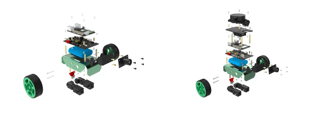
Hint:The installation steps are expected to take 30 to 60 minutes. You can refer to the following steps or the assembly instructions included in the kit.
During the installation, please note:
-
When securing screws, do not overtighten to avoid stripping;
-
When securing the boards, tighten the screws only after all four copper pillars or screws are secured;
1. Install the Robot Chassis
1.1 Install the Universal Wheels
Required materials:
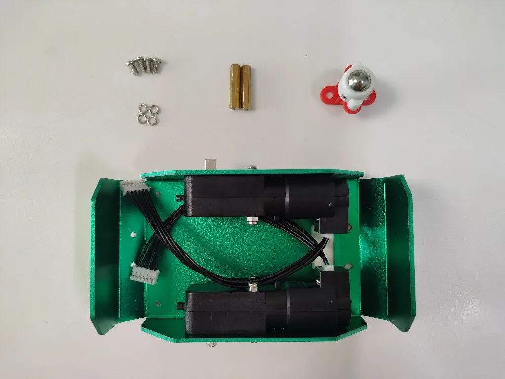
(1) Install the universal wheel support copper pillars
Find the two fixed holes for the copper pillars on the back of the robot chassis:
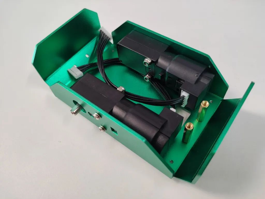
On the front of the chassis, use screws and washers to tighten the copper pillars:
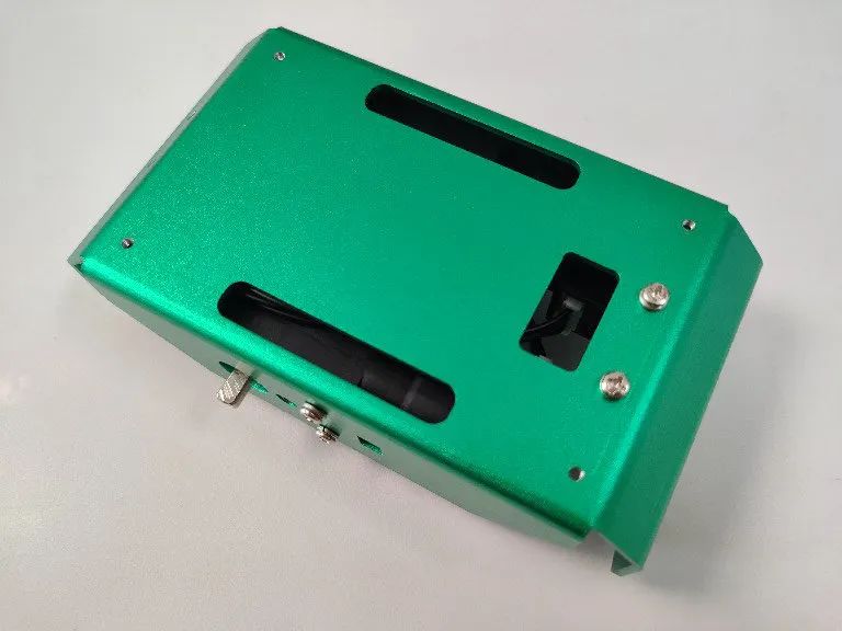
(2) Install the universal wheels
Use screws and washers to secure the universal wheels at the ends of the copper pillars:
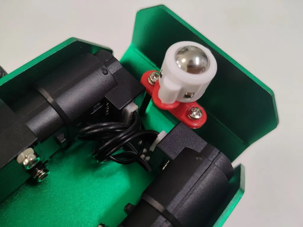
1.2 Install the Controller Support Copper Pillars
Required materials:
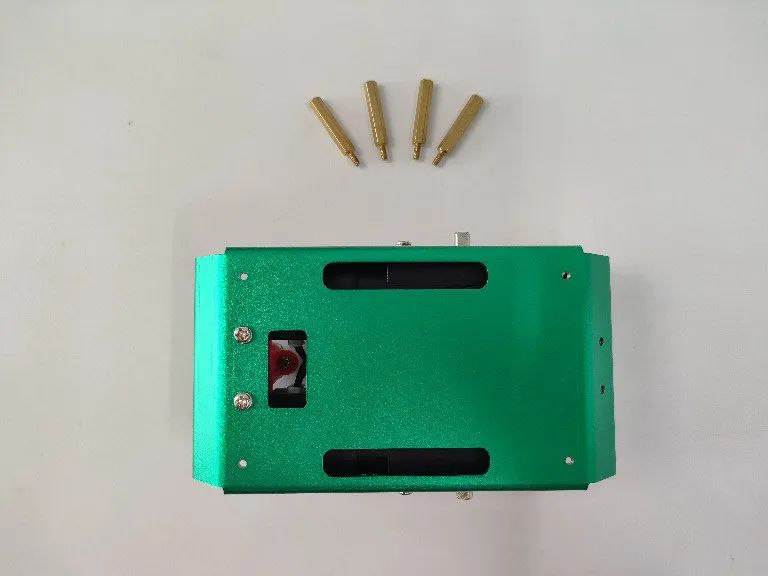
The fixed holes on the chassis come with threading, simply screw in the four copper pillars:
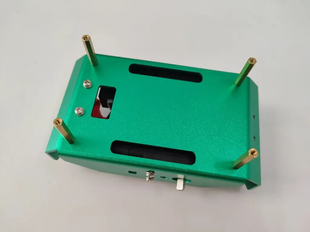
1.3 Install the Power Battery
Required materials:
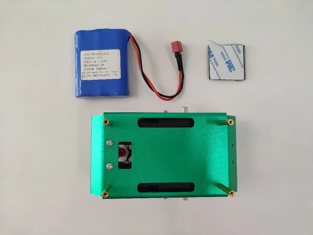
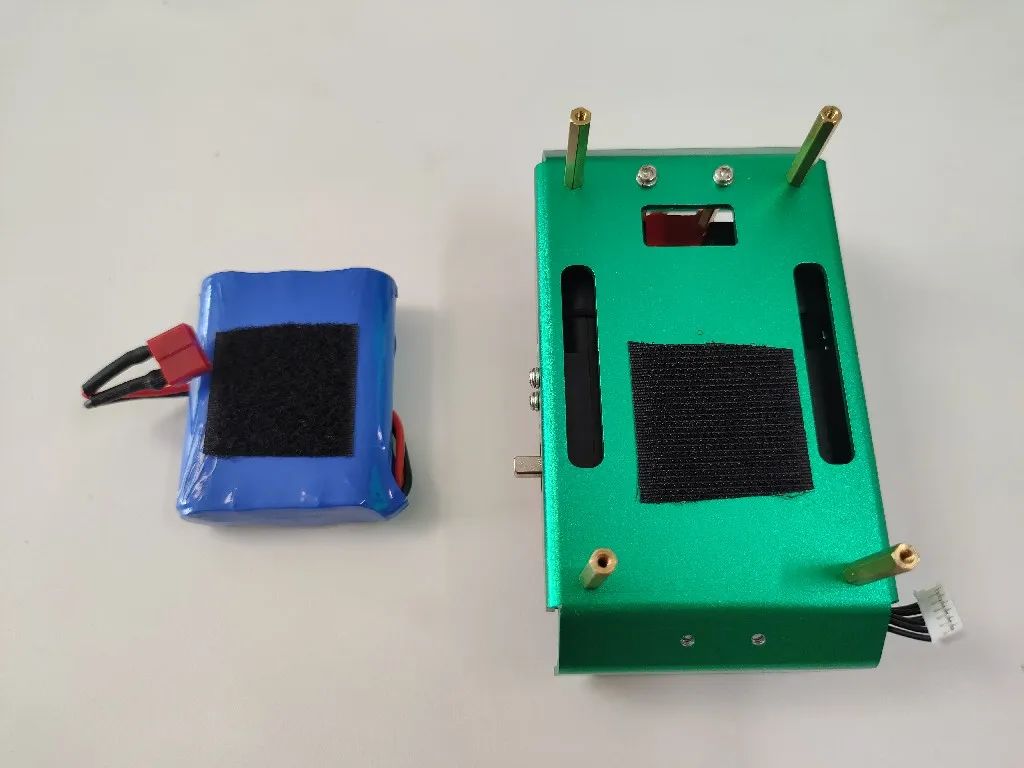
(1) Install the Velcro
Peel off the double-sided tape from the Velcro and stick it to both the chassis and the battery:
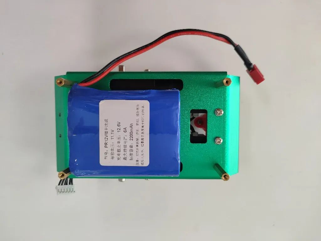
(2) Install the battery
Use Velcro to secure the battery to the chassis, placing it as close to the left side as possible to ensure the center of gravity is on the motor axis:
1.4 Install the Wheels
Required materials:
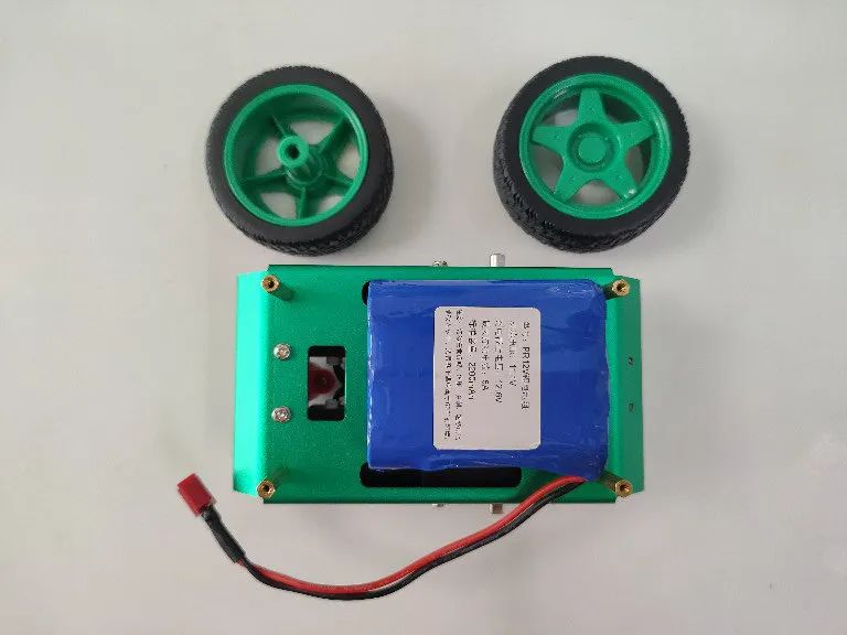
(1) Install the wheels
Press the two wheels onto the motor shafts on either side of the chassis:
Hint:Be careful with the force to avoid damaging the motor.
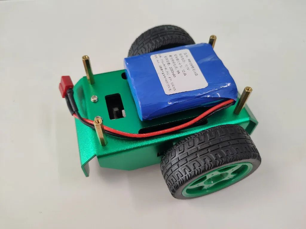
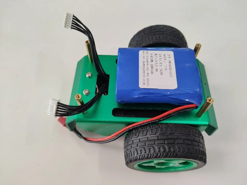
(2) Organize the motor wires
Pull the wires from both motors through the chassis for easier wiring later, ensuring the motor connections are secure to avoid poor contact:
2. Install the Controller Board
2.1 Install the Upper Support Copper Pillars of the Controller
Required materials:
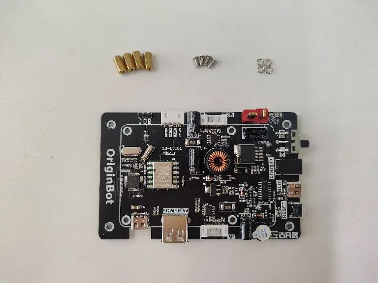
Place the copper pillars in the front holes of the controller and tighten using screws and washers from the back:
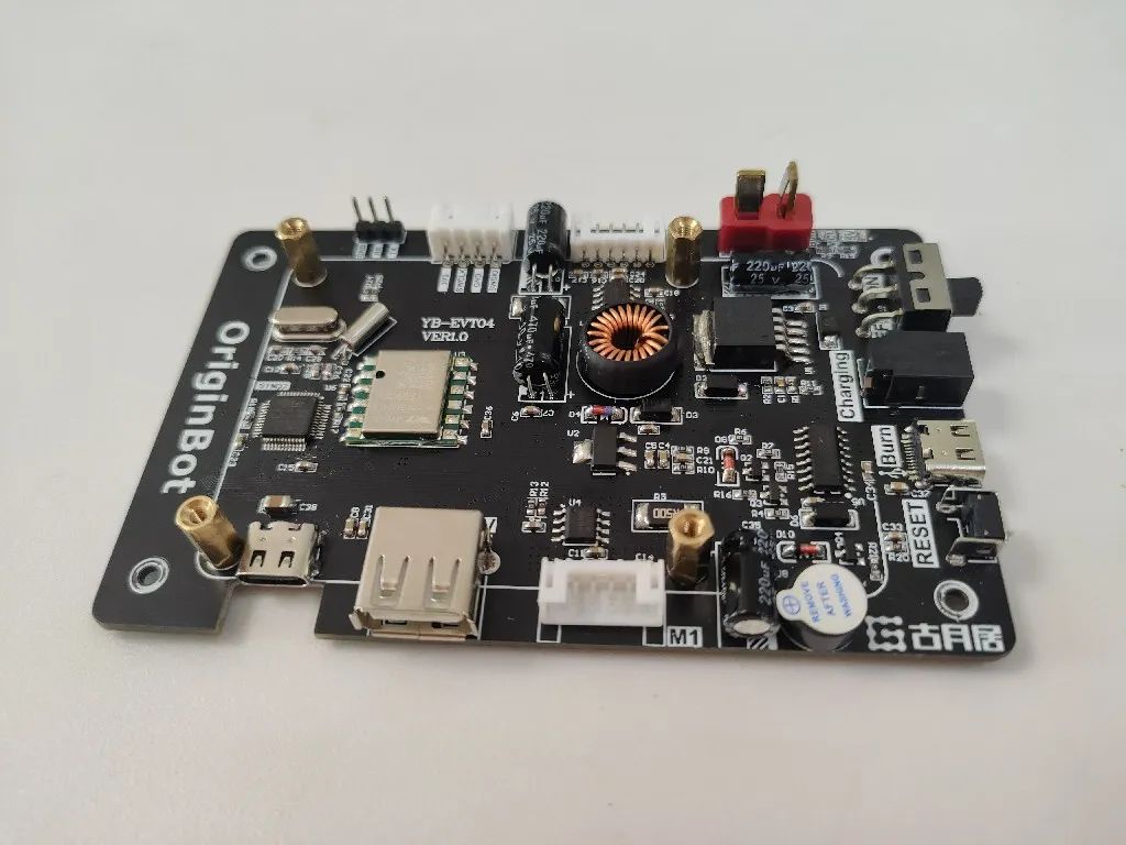
2.2 Install the Controller Board
Required materials:
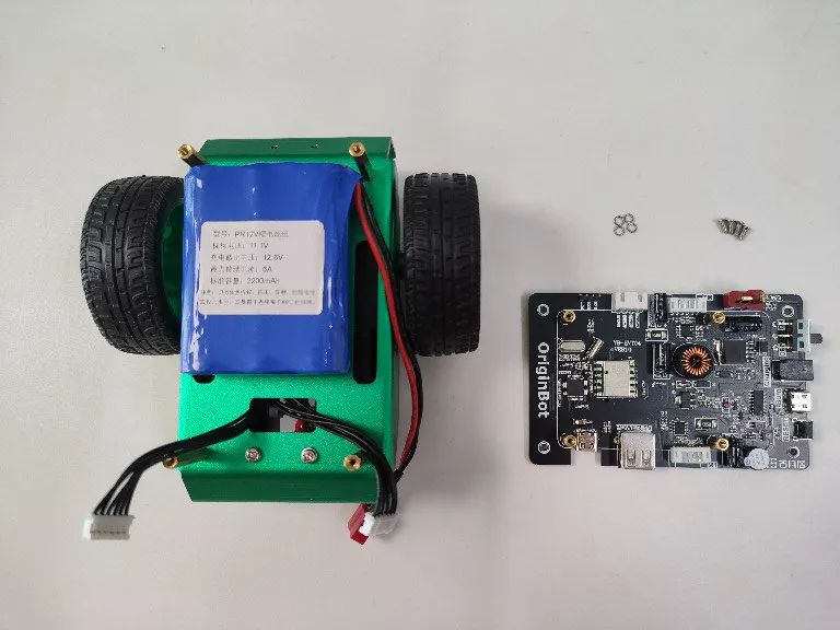
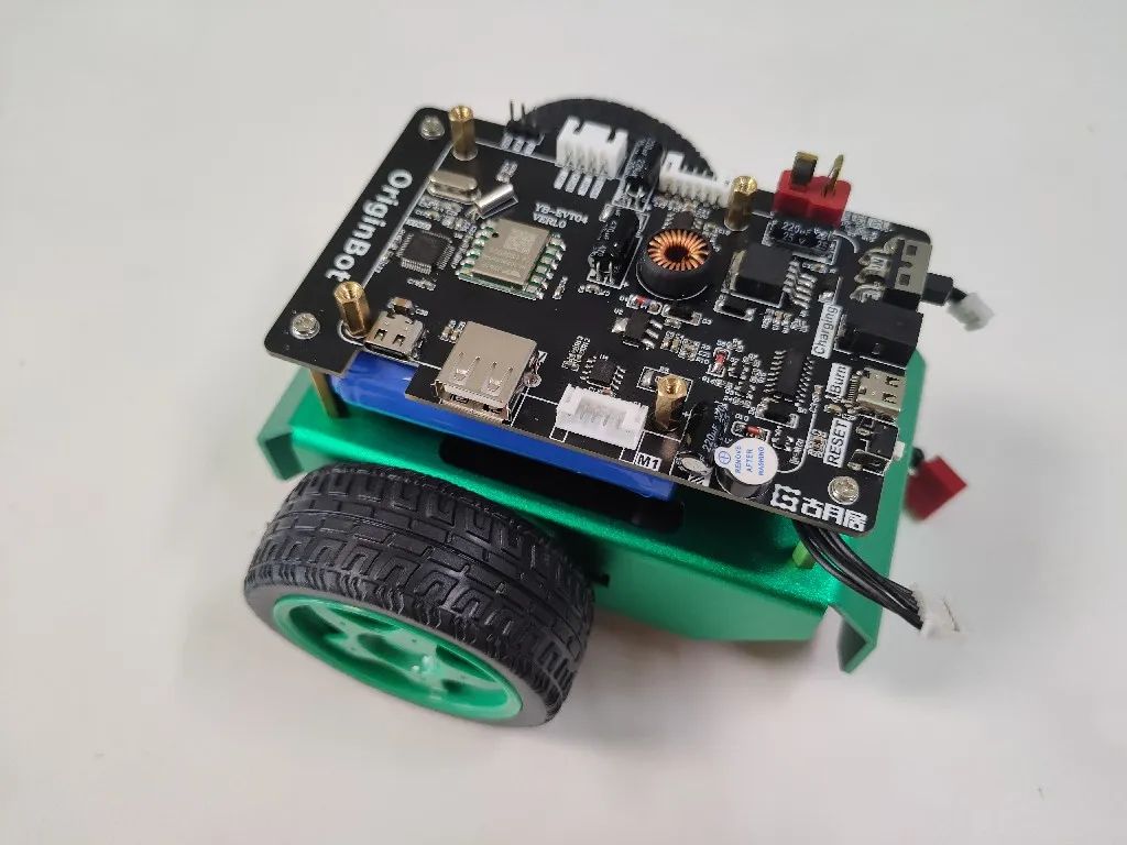
Use screws and washers to secure the controller to the four support copper pillars on the chassis:
2.3 Connect the Motor Wires
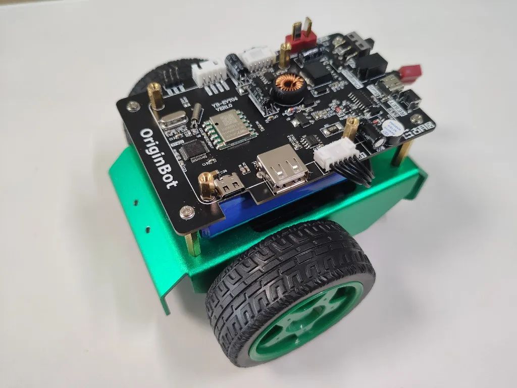
Connect the previously pulled motor wires to the corresponding ports on the controller:
Hint:Pay attention to the motor interface numbers; connect the left motor to the left control interface and the right motor to the right control interface;
When inserting into the white port, it is recommended to use the other hand to press down on the controller end to avoid excessive force causing it to lift;
At this point, do not connect the battery power line to prevent subsequent misoperation;
3. Install the Processor Board
3.1 Install the Processor Heat Sink and Antenna
Required materials:
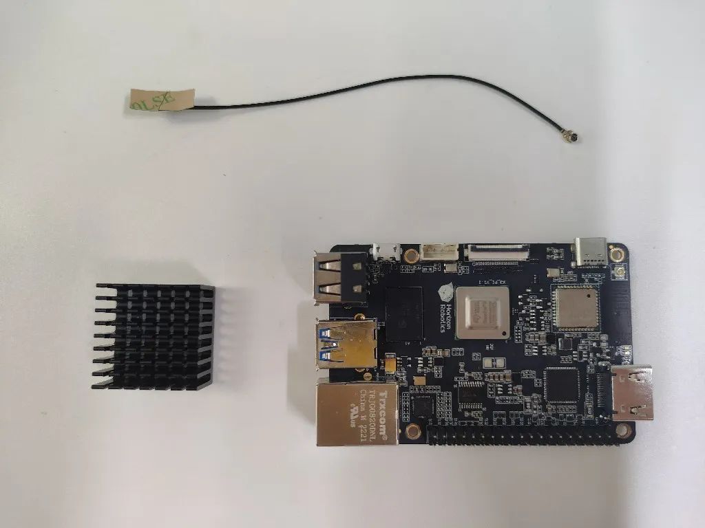
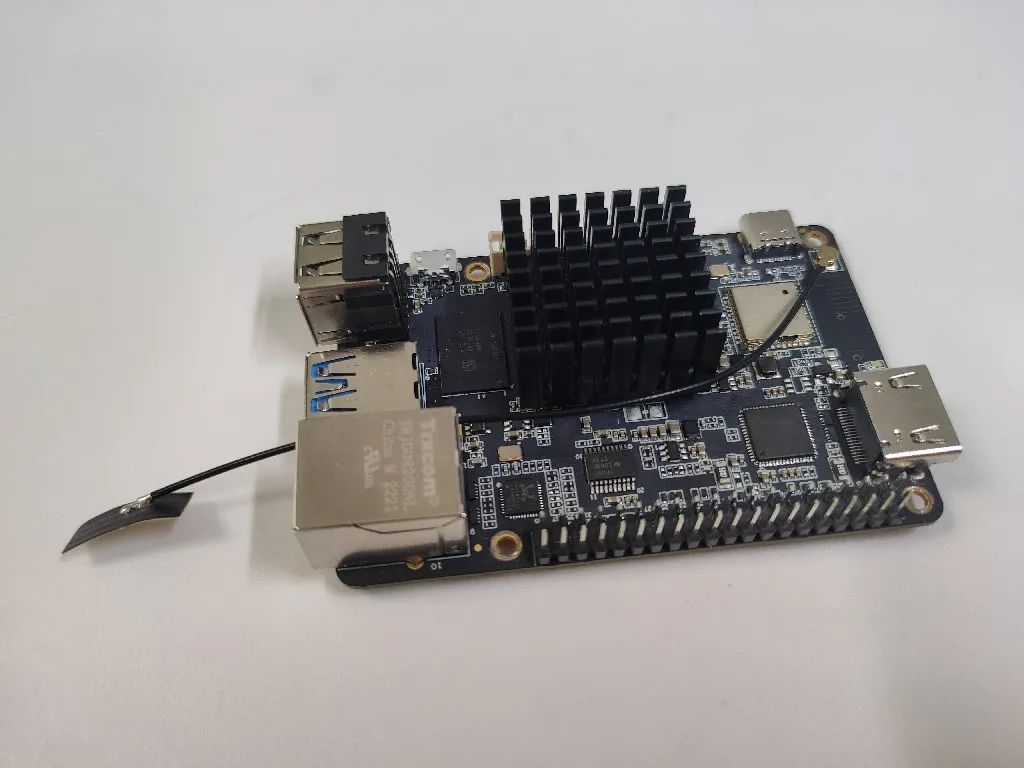
Peel off the blue sticker on the back of the heat sink and use the included white adhesive to attach it to the core SoC of the X3 Pi;
Then press the antenna onto the corresponding interface on the board:
Hint:The end of the antenna has adhesive; if needed, it can be attached to the network port or another suitable location, but it can also be left unglued.
3.2 Install the Processor Board
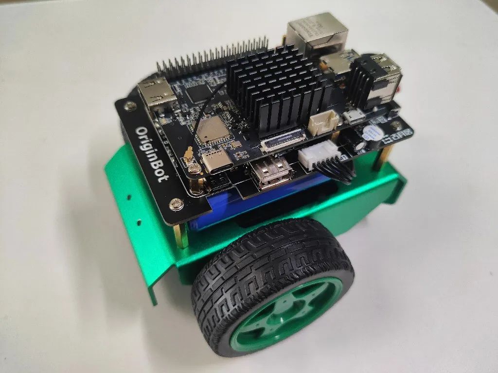
(1) AI Vision Version
Required materials:
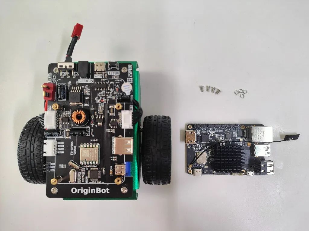
If you do not need to install the LiDAR, you can directly install the X3 Pi onto the supporting copper pillars on the controller using screws and washers:
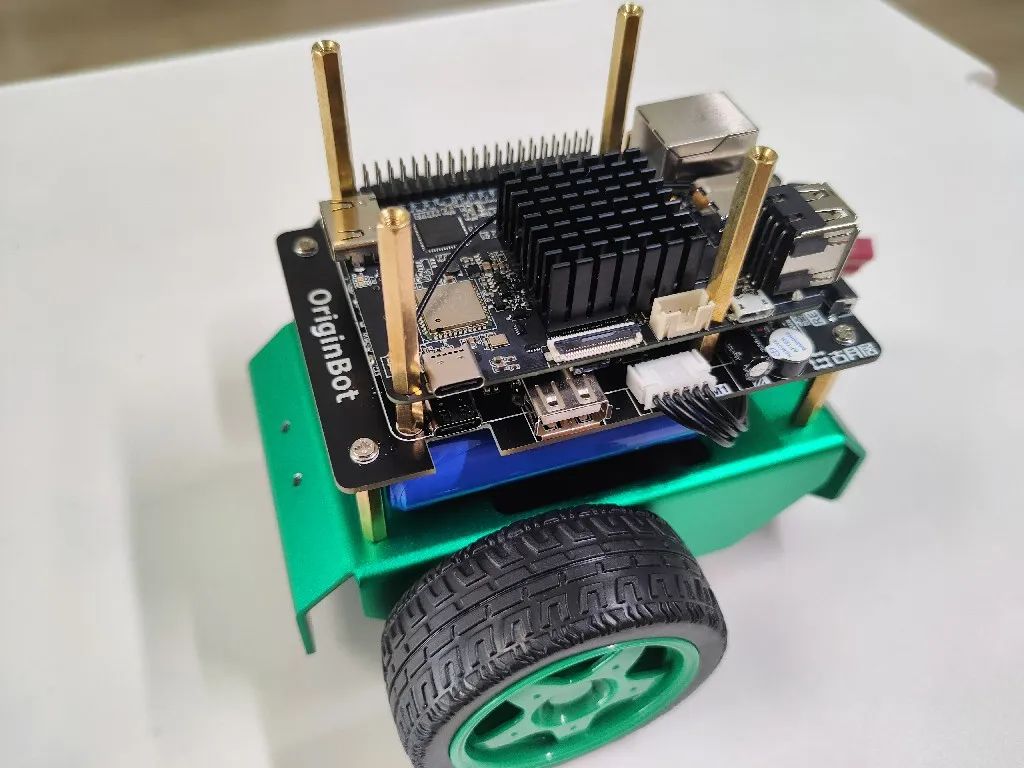
(2) Autonomous Navigation Version
Required materials:
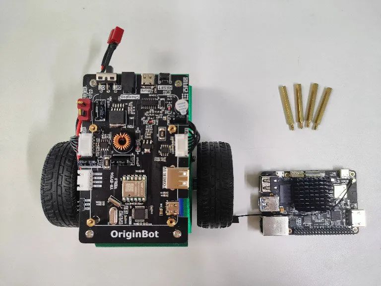
If you need to install the LiDAR, you can use four copper pillars to install the X3 Pi onto the supporting copper pillars of the controller:
4. Install the Camera
4.1 Install the Camera Module
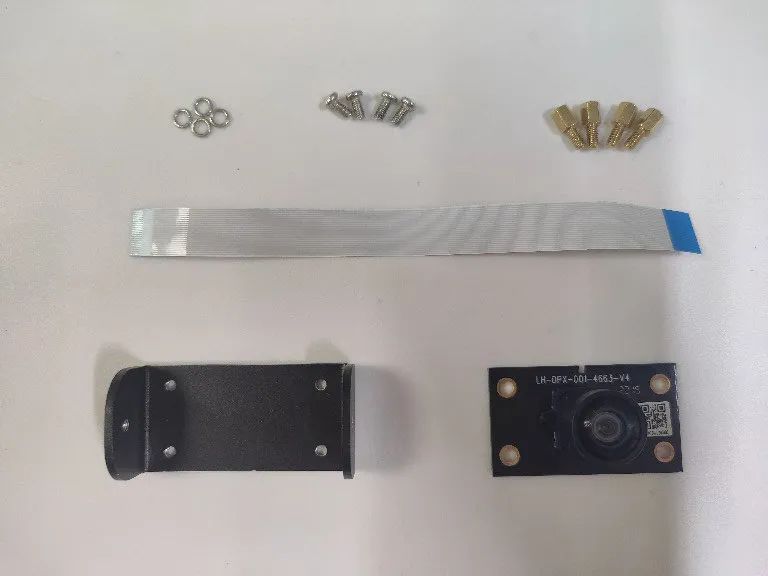
Required materials:
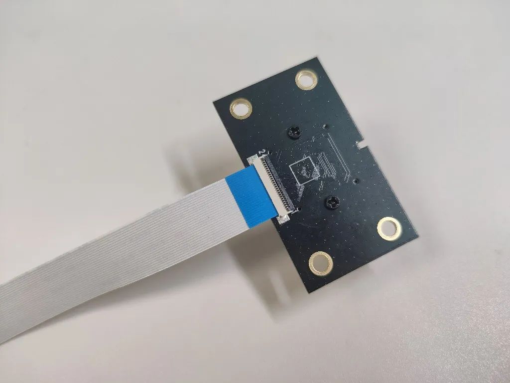
(1) Connect the camera data cable
Gently press the black buckle on the back of the camera, insert one end of the ribbon cable into the port, and then press the black buckle to complete the connection:
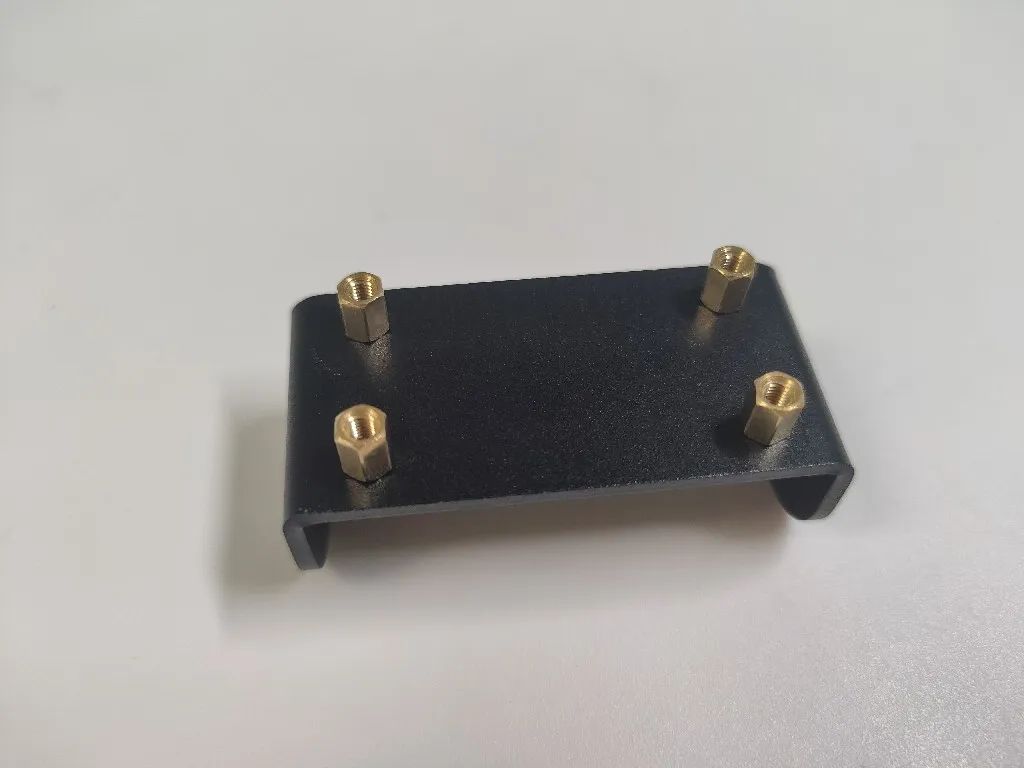
(2) Install the camera mount
The camera mount comes with threading, tighten the four copper pillars directly:
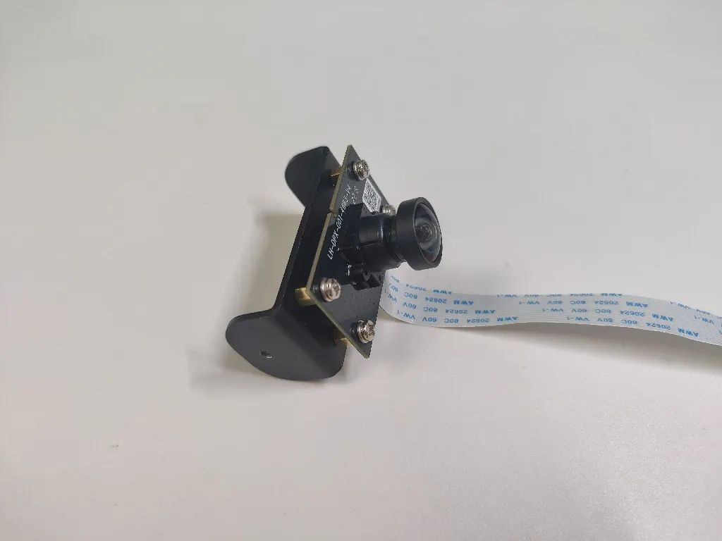
(3) Install the camera
Use four screws and washers to mount the camera module onto the mount:
4.2 Install the Camera
Required materials:
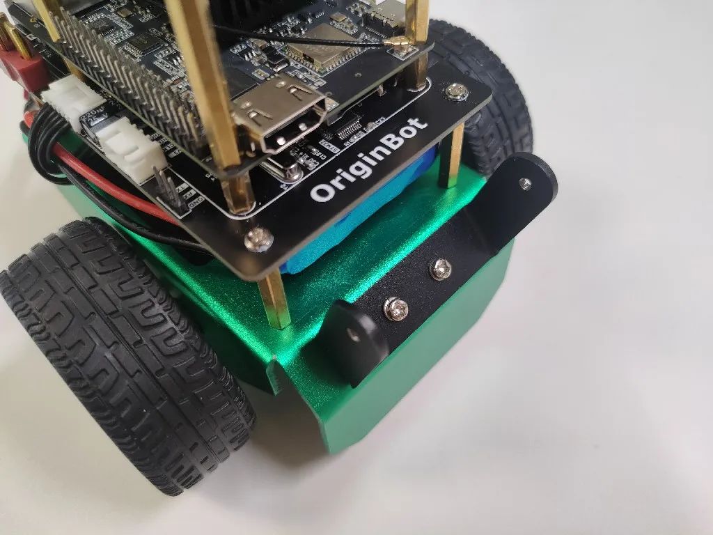
(1) Install the camera bracket
The installation holes on the chassis come with threading. Use two screws and washers to install the camera bracket onto the chassis:
(2) Install the camera mount
Use two hand-tightened screws to install the camera mount onto the bracket:
Hint:There needs to be enough friction between the camera mount and the bracket. If the camera cannot be fixed at an angle, you can slightly pull the camera mount outward with your hand before installing the fixed mount.
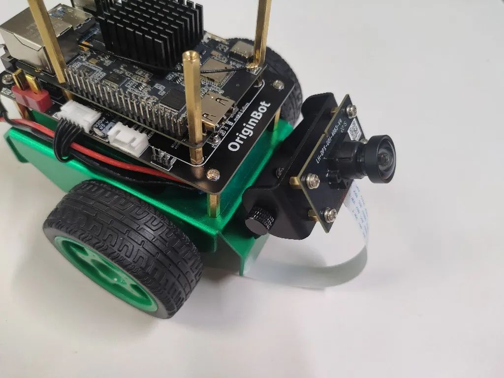
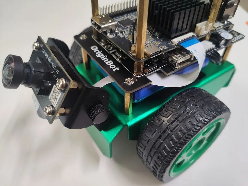
(3) Connect the camera data cable
Pass the camera’s ribbon cable through the space between the chassis controller and battery, and connect it to the interface on the X3 Pi:
5. Install the LiDAR
5.1 Install the Radar Serial Port Module
Required materials:
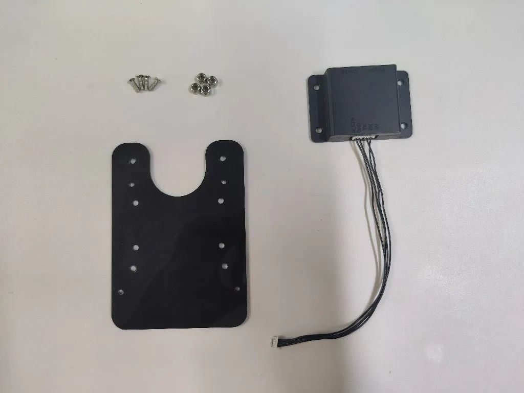
Peel off the protective film from the acrylic board and use four screws to install the radar serial port module onto the acrylic board:
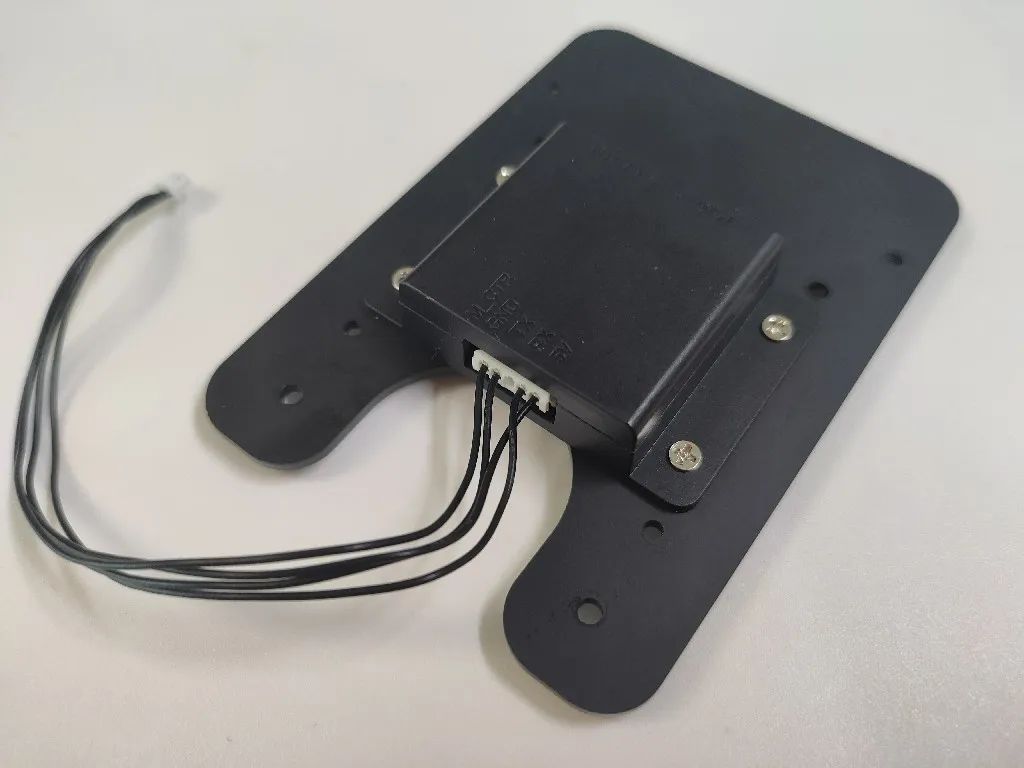
On the other side of the acrylic board, use four anti-slip nuts to tighten the screws:
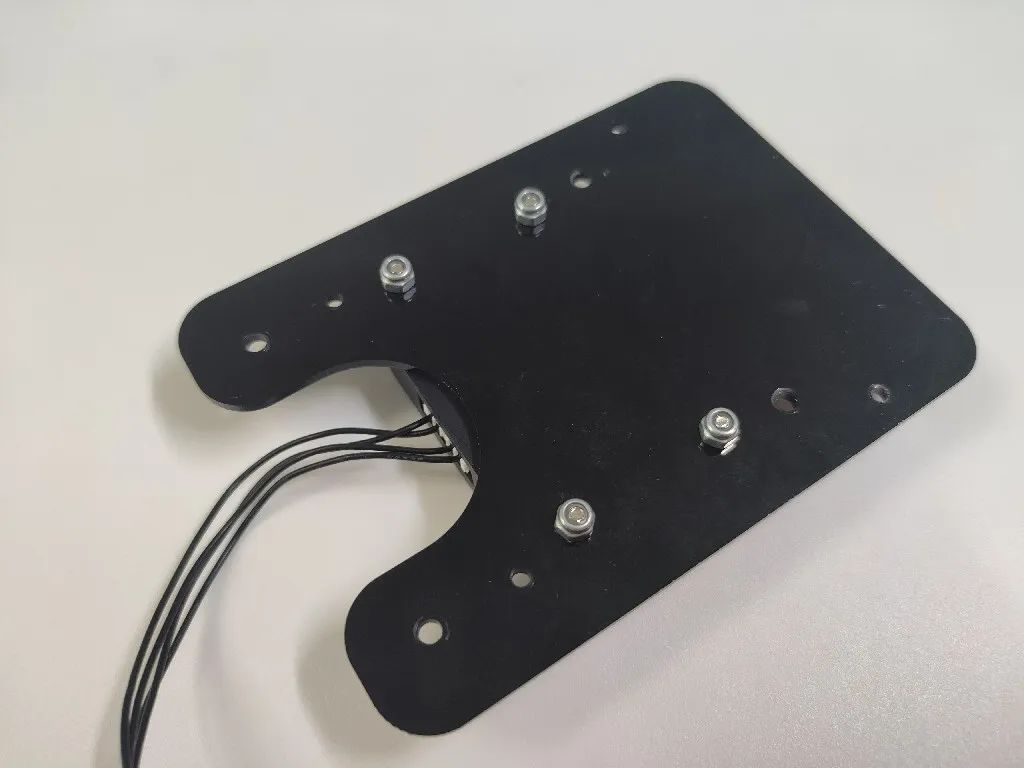
5.2 Install the Radar Bracket
Required materials:
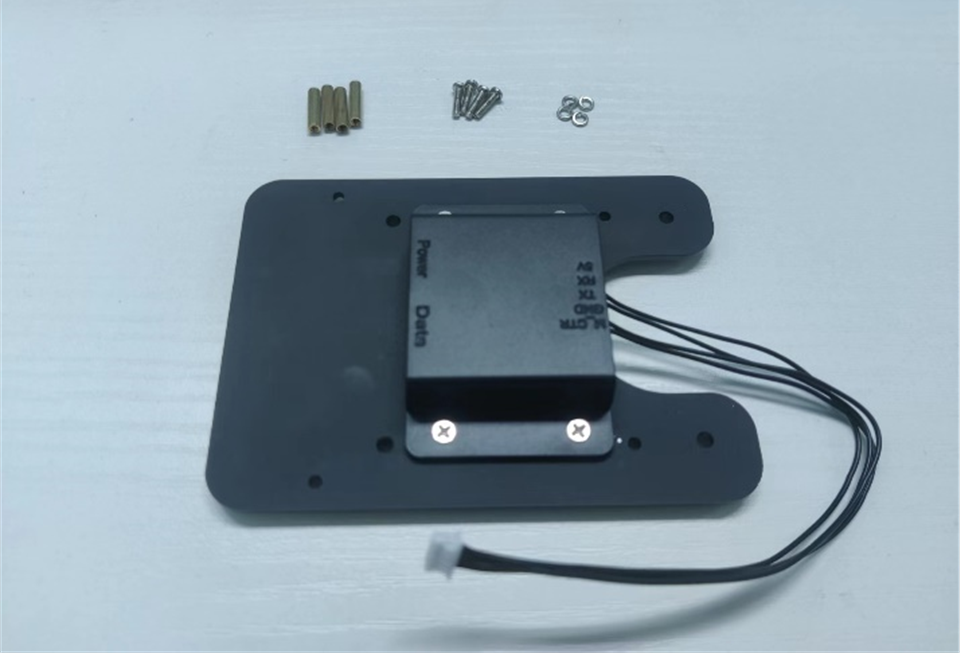
Pass the four copper pillars through the corresponding holes on the acrylic board:
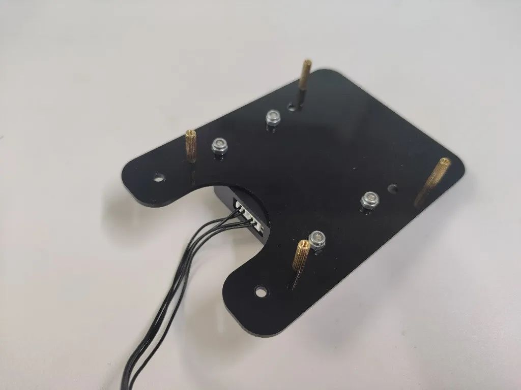
On the other side, secure with four anti-slip nuts and tighten the copper pillars:
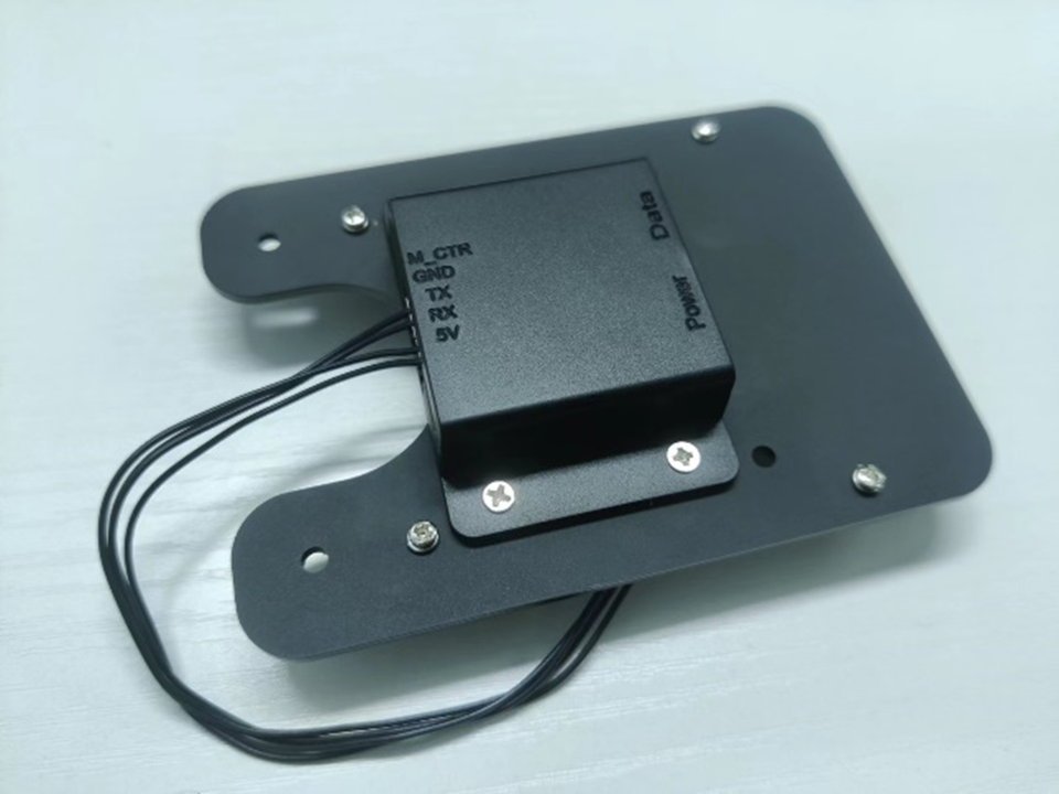
5.3 Install the Radar Acrylic Board
Required materials:
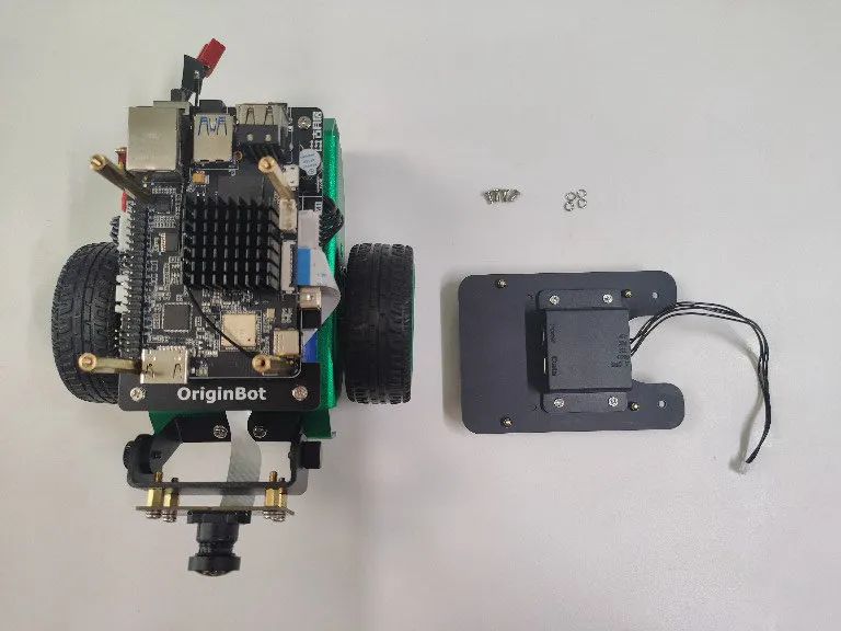
Use four screws and washers to install the acrylic board onto the four copper pillars on the X3 Pi:
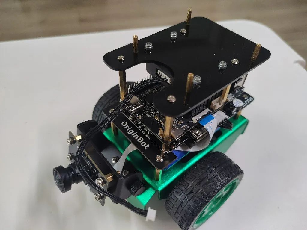
5.4 Install the Radar
Required materials:
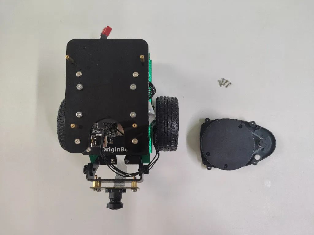
(1) Connect the radar serial line
Connect the radar serial port module’s output serial line to the corresponding interface on the back of the radar:
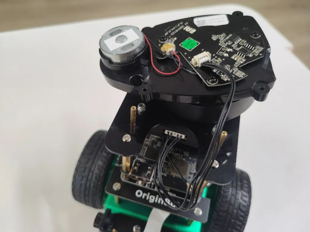
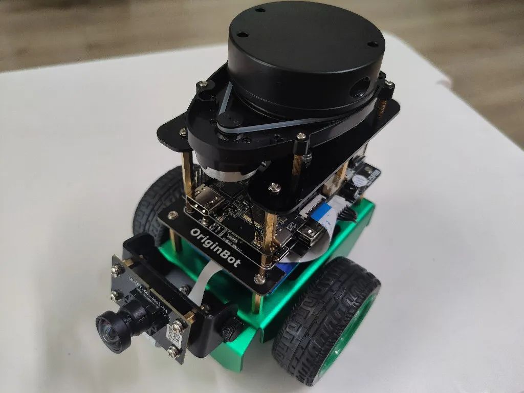
(2) Install the radar
Use four screws to secure the radar to the supporting copper pillars on the acrylic board:
6. Connect the Cables
Required materials:
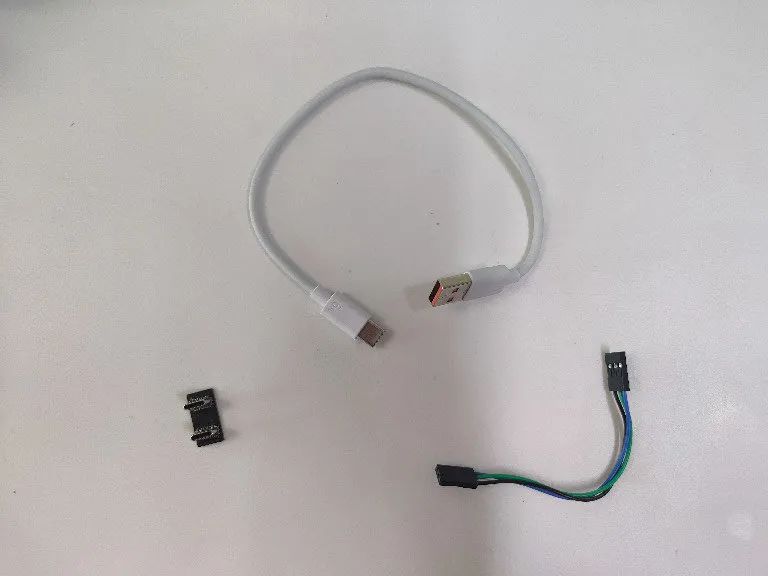
(1) Connect the power module
The X3 Pi is powered by the controller through the Type-C port. Use the Type-C power module to connect the controller’s power output to the X3 Pi’s power input:
Hint:When plugging and unplugging the Type-C power module, be careful with the force to avoid damaging the chip pins.
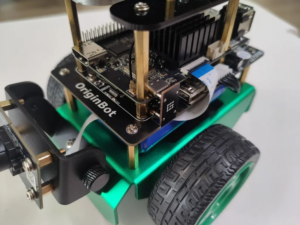
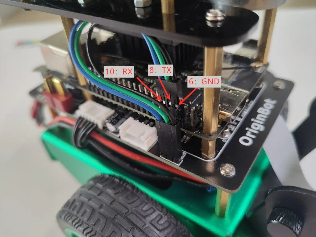
(2) Connect the serial communication line
Use the serial communication line to connect the controller and the X3 Pi’s communication interface:
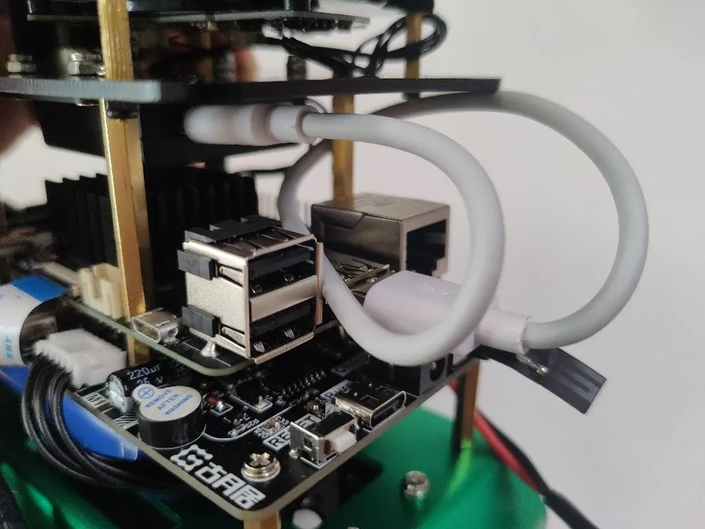
(3) Connect the radar communication line
The original Type-C data line for the radar is quite long. You can use the short line included in the kit, connecting one side to the USB port of the X3 Pi and the other side to the Type-C port of the radar serial port module:
(4) Connect the main power line
Check that all parts of the robot have been installed correctly according to the operation steps, and that the control switch is in the “OFF” position. Connect the main power line of the battery to the controller:
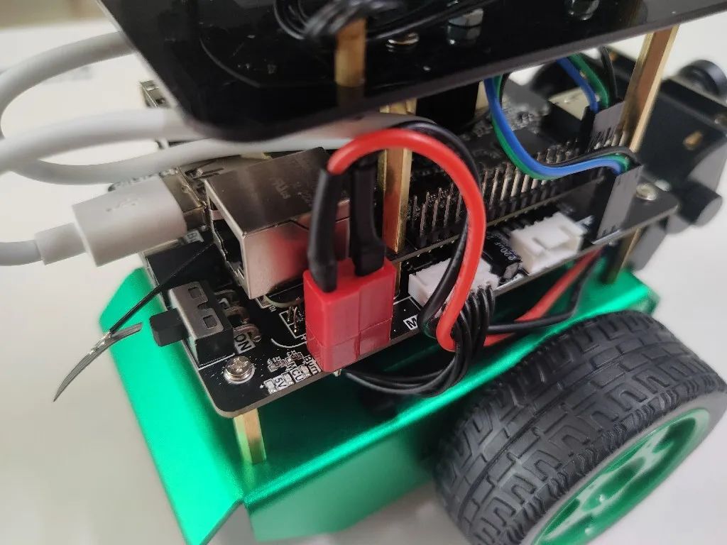
Hint:The power socket is quite tight and close to the X3 Pi, so please install it carefully. Aligning the two flat parts of the T-shaped plug close to the socket will make it easier to insert.
7. Install the License Plate and Radar Stickers (Optional)
Required materials:
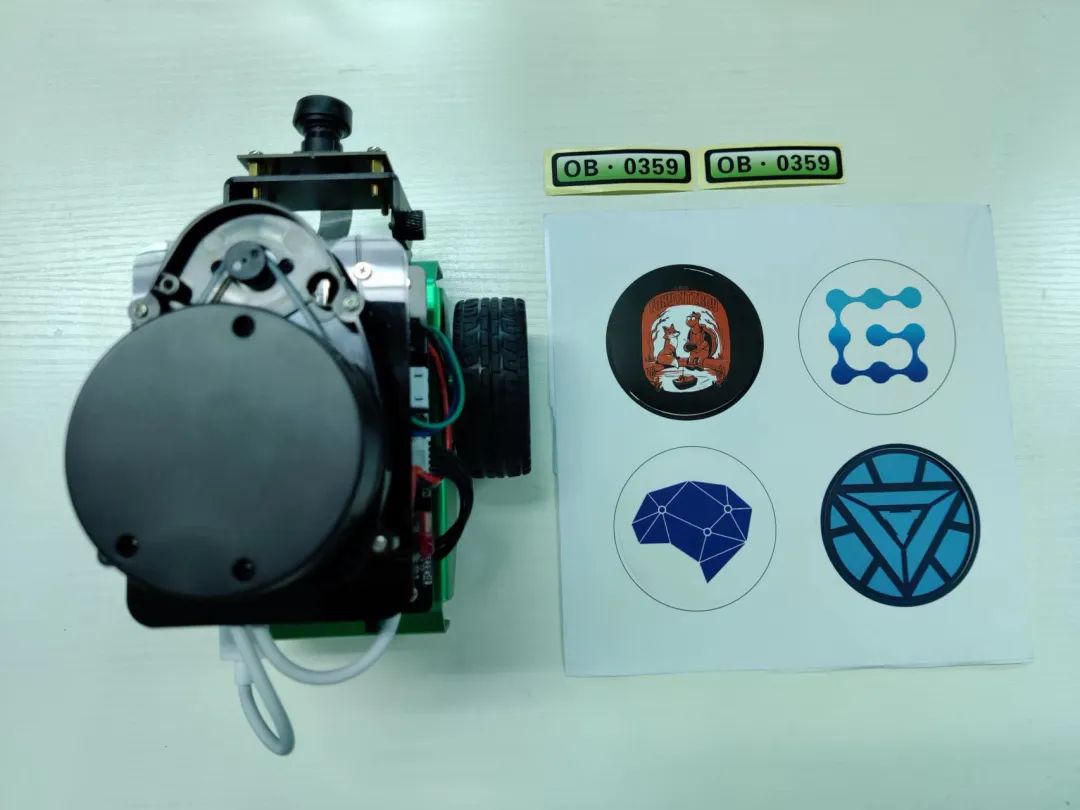
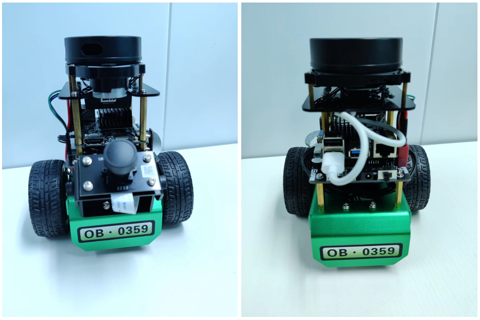
7.1 Stick the License Plate
As needed, stick the unique numbered stickers included in the kit to the front and back sides of the chassis.
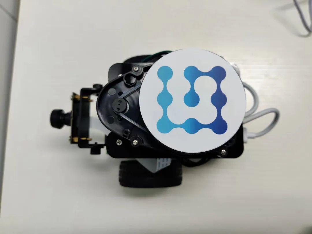
7.2 Stick the Radar Stickers
As needed, stick the radar stickers included in the kit to the top of the laser radar.
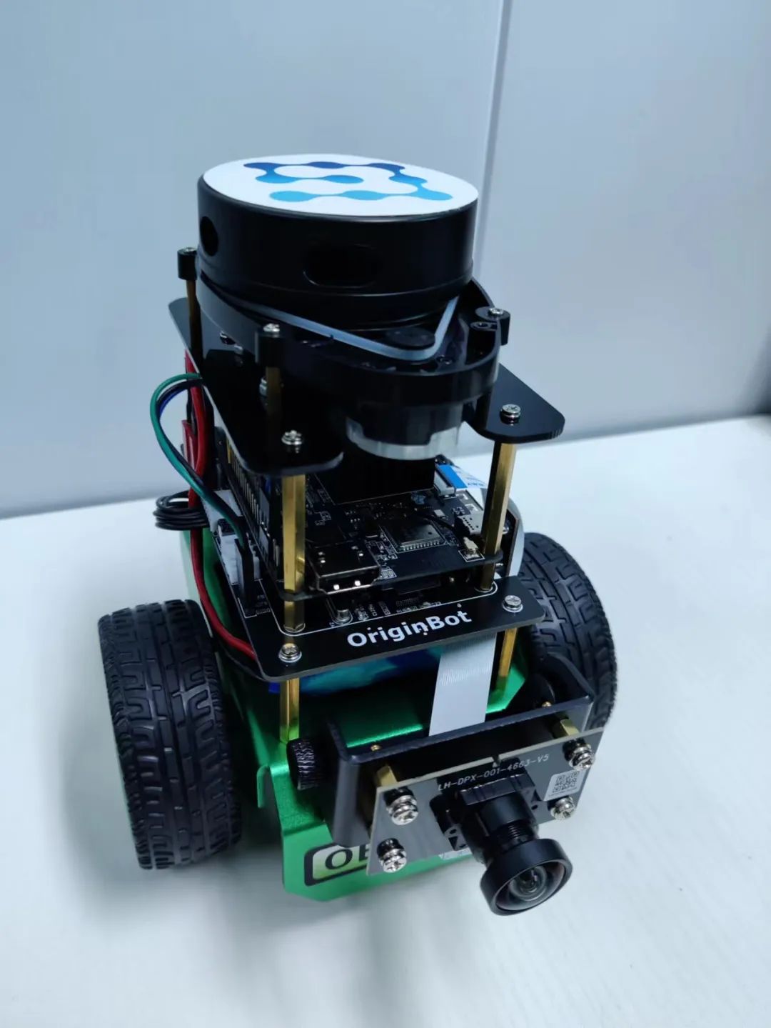
At this point, the OriginBot installation is complete.


《Developing Intelligent Vehicles from Scratch • Gu Yue & Qian Mo》
Created by the core team of Gu Yue Ju, this will guide everyone to design and develop an intelligent vehicle from scratch, covering knowledge across structure, electrical, embedded systems, ROS, artificial intelligence, and many other fields, quickly understanding the complete path of robot design and mastering the core methods of robot development.

(Scan the QR code for course details)