Today, let’s discuss some practical aspects related to UPF~~
1. Library Files
Taking TSMC‘s 7nm as an example, the naming of the lib library has four types (not corner, nor Vt): the first type has the name with “_BASE_“, which contains std cell; the second type has the name with “_MB_“, which contains multi-bit DFF; the third type has the name with “_LVL_“, which contains level-shifter and ELS; the last type has the name with “_PM_“, which contains isolation, retention and power switch.
First, let’s look at Level-shifter, which can be classified into three types based on the direction of level conversion: high to low, low to high, and both low to high and high to low. Depending on the placement, Level-shifter can also be divided into source and destination.
Similarly, for Isolation cell, it is also divided into source and destination. Based on the clamping values, isolation can be classified into 0 and 1 types. Here, the 0 type can be understood as an “AND” gate, where the control signal iso_en has an effective value of 1‘b0, while the 1 type is an “OR” gate, where the control signal iso_en has an effective value of 1‘b1.
Careful readers may notice a problem: what if both level conversion and isolation are needed? In this case, an ELS (Enabled Level-shifter) is required, which is a level-shifter with an enable signal, where iso_en is connected to the enable terminal of the ELS.
In TSMC‘s library, there are three types of single level-shifter:
-
Low to high, destination (LVLLHBUFFSNKCWD)
-
Low to high, source (LVLLHBUFFSRCCWD)
-
High to low, destination (LVLHLBUFFSNKCWD)
There are four types of single isolation:
-
Clamping value 0 of source type (ISOCLSRCIWD)
-
Clamping value 0 of destination type (ISOCLSNKCWD)
-
Clamping value 1 of source type (ISOCHSRCIWD)
-
Clamping value 1 of destination type (ISOCHSNKCWD)
For ELS, there are five types:
-
Low to high, clamping value 1, destination type (LVLLHCHSNKCWD)
-
Low to high, clamping value 1, source type (LVLLHCHSRCCWD)
-
Low to high, clamping value 0, destination type (LVLLHCLSNKCWD)
-
High to low, clamping value 1, destination type (LVLHLCHSNKCWD)
-
High to low, clamping value 0, destination type (LVLHLCLSNKCWD)
The choice of which type to use depends on the specific low power strategy implementation plan. It is important to note that the above content may be outdated, as the library files may have been updated.
2. Troubleshooting
Personally, I feel that there is a concept in UPF that is not easy to understand, which is HighConn and LowConn. In the IEEE Std 1801 documentation, they are defined as follows:
-
HighConn: The side of a port connection that is higher in the design hierarchy; the actual signal associated with a formal port definition.
-
LowConn: The side of a port connection that is lower in the design hierarchy; the formal port definition.
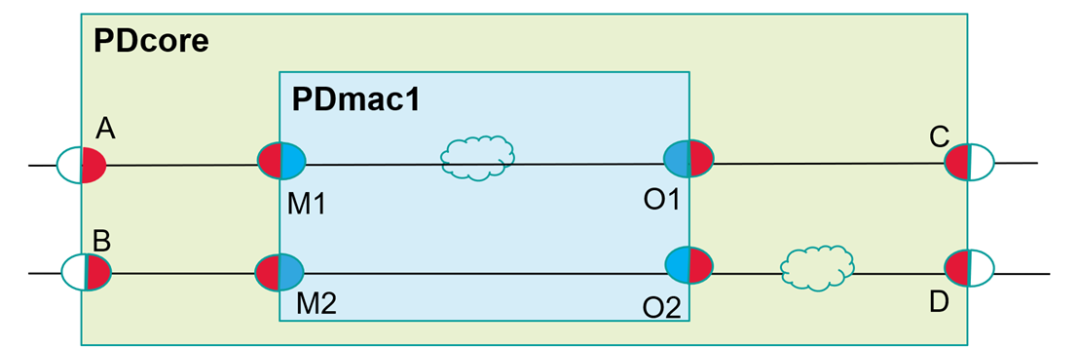
Understanding HighConn and LowConn is crucial for level-shifter and isolation. A port is divided into two halves, LS and ISO acting on the half port, if high-conn and low-conn are in the same domain, then LS and ISO cannot be added. The following diagram illustrates this, where M1‘s blue half is Lowconn in PDmac1, and the red half is HighConn in PDcore.
The following example can help with understanding:
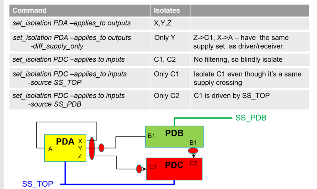
At this point, we need to look at specific UPF commands, set_level_shifter and set_isolation, which are similar; analyzing one is sufficient. Below is the command format from IEEE Std 1801.
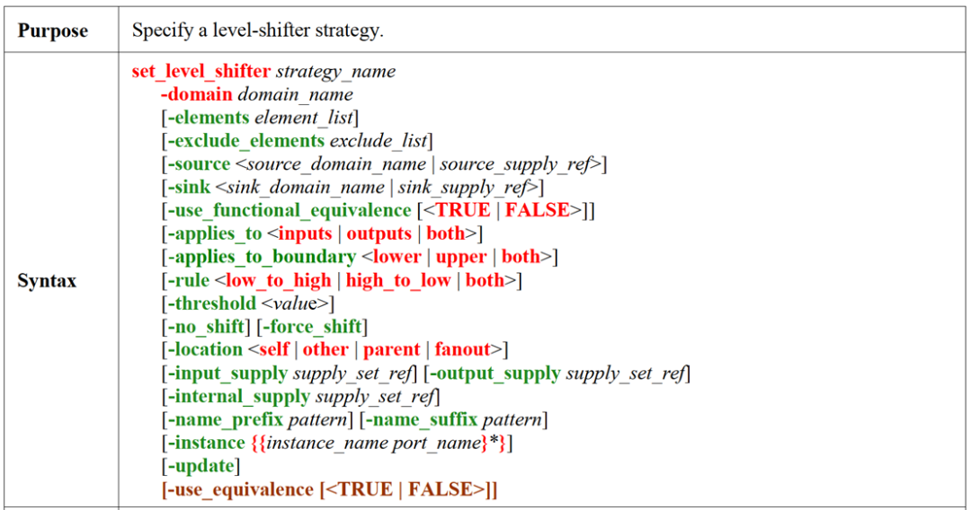
It seems there are many options, but they can mainly be divided into two categories:
The first category is how to set the filter, how to filter out the ports that need to add LS or ISO: the previously mentioned HighConn and LowConn are related to this part:
-
-applies_to
-
-elements
-
-exclude_elements
-
-sink,
-
-source
It is important to note that these filtering options have priorities, which can be referenced in the IEEE Std 1801 spec.
The second category is how to add, whether it is high to low or low to high, where the level-shifter/isolation cell power supply is connected:
-
-rule
-
-location
-
-input_supply
-
-output_supply
-
-internal_supply
Therefore, when writing UPF, it is essential to clearly understand the attributes of each port‘s /source/destination, so as to ensure that UPF aligns completely with the design intent.
At this point, there may still be a question: how to set the port‘s HighConn and LowConn? This requires the use of set_port_attributes.
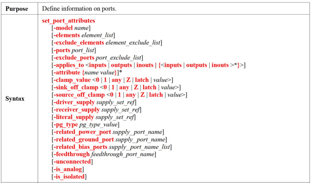
If the set_port_attributes command is not used to declare the port attributes, it defaults to belonging to the current power domain.
For each port, there should be three fundamental questions: “Who am I? Where do I come from? Where am I going?”.
It is strongly recommended that all ports have their attributes explicitly specified, do not find it troublesome, to avoid errors. To facilitate better setting of port attributes, a certain naming convention can be applied during logical design to categorize the ports, and then use the find_object command to extract this type of signal.
3. Recommendations
Each EDA company has different support for UPF, and even different EDA software from the same company may not fully support UPF. Therefore, if you are writing UPF, you can refer to the following suggestions, so that the written UPF can better adapt to different tool flows:
-
Try to use the conventional options of UPF, as most tools have consistent support for conventional options;
-
If certain option values are determined, try to explicitly declare them in UPF, even if the declared value is the default value, because sometimes different tools have different default values for a certain option;
-
Try to explicitly declare the UPF corresponding design port attributes. If not declared, all ports will be classified into the power domain of the design. For large-scale designs, declaring the attributes of each port can indeed be very cumbersome; first, it is not easy to figure out which power domain each port goes to/comes from, and then listing them one by one is also laborious. However, the benefit of doing this is that it will reduce the number of iterations of UPF, and it will not be discovered late in the process that some port attributes are incorrect. Moreover, UPF provides the find_object command, which supports * wildcard, which can reduce the work of declaring ports to some extent.
-
For low-power design strategies (level-shifter, isolation, power switch, retention), it is also best to define them explicitly in UPF. Some tools claim to have intelligent automatic inference functions, for example, if two different voltage domains are defined in UPF, even if set_level_shifter is not defined, the tool can infer that signals between the two voltage domains need level conversion. However, it is not recommended to do this, as such UPF is difficult to port to other tools and may increase the risk of different tools interpreting the design intent differently.
* Disclaimer: This article is original by the author. The content reflects the author’s personal views, and the reproduction by LuKe Verification is solely to convey a different perspective, not representing LuKe Verification’s endorsement or support of this view. If there are any objections, please feel free to contact LuKe Verification.