
In multi-voltage design, isolation cells are often used. This article briefly introduces what an iso cell is, how to use an iso cell, when to add an iso cell, and the insertion position of the iso cell.
1. What is an iso cell?
An isolation cell, typically used in Power Shutdown (PSO) and Multi-Supply Multi-Voltage (MSMV) technologies, serves to clamp and isolate voltages between different voltage domains.
An isolation cell acts as an interface between the shutdown module and the always-on module, isolating two different power domains.
The schematic of an isolation cell is as follows:
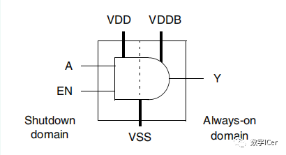
The iso cell has a control terminal EN. When EN is inactive, the signal at terminal A is directly sent to terminal Y, making the iso cell equivalent to a buffer. When EN is active, the buffer disconnects, and terminal Y maintains a fixed high or low level.
To ensure that the isolation cell can still function during power down, it generally has a primary power and a secondary power, the latter ensuring that the device continues to operate when the former is powered down.
As shown in the figure above: the iso cell has two power supplies: primary power VDD and backup power VDDB. When the left domain is turned off, VDD goes off, and VDDB supplies power to maintain the fixed level at terminal Y.
2. How to use an iso cell?
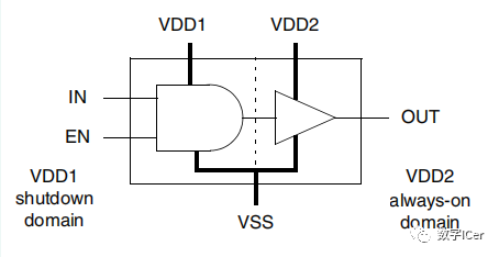
Typically, isolation cells are used in conjunction with Level Shifters, and both AND and OR gates can form an isolation cell.
1. AND type: output iso to 0;
2. OR type: output iso to 1;
3. When to use an iso cell?
When a signal passes from one module to another, if the power of the shutdown module is turned off, the output signal may show unpredictable values. If this value is passed to the always-on module, it may cause functional issues. Therefore, it is necessary to isolate the output signal of the powered-off module from other modules by adding an isolation cell (ISO) to all boundary signals.
The role of the isolation cell is to fix a certain signal potential to a high or low level after the power is turned off, ensuring that the output signal is a definite value (1 or 0). As shown in the figure below:
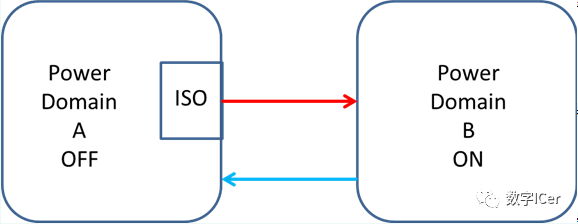
When a signal passes from an off domain to another domain (on or off), if domain A is turned off while domain B is still running, B’s input may float, potentially causing errors due to undefined input states. Therefore, when the signal moves from A to B, an iso cell is required to ensure that A’s output signal remains at a stable level when A is turned off.
4. Insertion position of the iso cell?
Regarding the insertion position of the isolation cell, we need to decide whether to place it within the power gated module (source module) or the always-on module (destination module).
-
Placing it at the output end of the source module can save the number of required isolation cells. Considering the case where an output pin of one module connects to the input pins of multiple modules, it also facilitates inspection.
-
Placing it at the input end of the destination module has the advantage that the isolation cell requires always-on power. If placed at the output end of the source module, it would still need to connect to the always-on power rail. (Considering the routing of the power-on rail and the power consumption of the isolation cell, it is generally better to place it at the input end, as this does not require always-on power.)
Regardless of where it is placed, the power connections need to be noted: The placement of isolation must have both gated power and always-on power present and correctly connected both physically and logically. Therefore, it is common to designate a fixed area for the isolation cell, where two different power stripes and power rails can be connected, or to let the tools automatically route the secondary power connection, the latter mainly appearing in non-advanced processes.
Summary:
Where can the isolation cell be placed, or can it be independent? This can be considered from several angles:
1) Power issues of the isolation cell.
The significance of the isolation cell’s operation is that the power-gated domain does not affect the always-on domain, so it should not use the power of the power-gated domain.
Therefore, it is better to place the isolation cell in the always-on domain or independently.
2) Number of isolation cells. For a power-gated domain:always-on domain ratio of 1:n, to achieve one isolation cell controlling all outputs, there are two choices: power-gated domain and independent. The always-on domain cannot achieve this.
3) Area occupied by the isolation cell. If the isolation cell is independent, the area occupied by a single isolation cell can be slightly larger. Thus, the position of the isolation cell is related to the specific scenario and is not unique.
If the power-gated domain:always-on domain ratio is 1:1, placing it in the always-on domain should be the optimal solution, as it can directly use the power, has a quantity of 1, and occupies the least area.
Note:
1) Power-gated domain: a domain where power can be turned off, i.e., in low power mode, it is in the off state.
2) Always-on domain: a domain where power is always on, i.e., the main processing domain of the device, where the power state cannot be turned off.
Below is the lib iso cell:
cell(Isolation_Cell) {
is_isolation_cell : true;
dont_touch : true;
dont_use : true;
pg_pin(VDD) {
 voltage_name : VDD;
 pg_type : primary_power;
}
pg_pin(VSS) {
 voltage_name : VSS;
 pg_type : primary_ground;
}
...
pin(A) {
 direction : input;
 related_power_pin : VDD;
 related_ground_pin : VSS;
 isolation_cell_data_pin : true;
}
pin(EN) {
 direction : input;
 related_power_pin : VDD;
 related_ground_pin : VSS;
 isolation_cell_enable_pin : true;
}
pin(Y) {
 direction : output;
 related_power_pin : VDD;
 related_ground_pin : VSS;
 function : "A * EN";
 power_down_function : "!VDD + VSS";
 timing() {
 related_pin : "A EN";
 cell_rise(template) {
 ...
 }
 ...
}
...
}
References:
- <Synopsys®Low-Power Flow>
- https://aijishu.com/q/1010000000133347
- https://www.sohu.com/a/220628287_99933533
- https://www.cnblogs.com/xiaoxie2014/p/10837155.html
- https://blog.csdn.net/qq_36480087/article/details/111589349