Skip to content
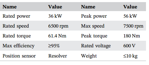
As part of electric vehicles, motors and controllers are usually mass-produced. To reduce costs, controllers typically adopt modular components for assembly, facilitating automated production, testing, and maintenance. Reducing the number and variety of parts can also lower inventory and management costs. A 600 V/36 kW/5600 rpm permanent magnet synchronous motor controller has been designed for electric vehicles. The technical parameters of the permanent magnet synchronous motor controller are shown in the table below.
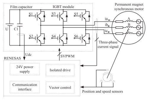
The hardware of the electric vehicle permanent magnet motor controller mainly consists of high-voltage film capacitors, main circuit IGBT (Insulated Gate Bipolar Transistor) modules, opto-isolated drives and protections, 24V power supply modules, and current and voltage detection modules, as shown in the figure below.
The motor controller includes high and low voltage circuits, signal circuits, power circuits, digital circuits, and analog circuits. The high frequency of digital signals can interfere with analog circuits, hence the controller is divided into two parts: the control board and the drive board, to prevent high-frequency signals from affecting the operation of the drive board. Signal transmission between the control board and the drive board uses opto-isolation technology to effectively reduce interference and improve system reliability. The PWM signal transmission path and feedback signal processing path are partially separated to minimize cross-transmission, ensuring that signals in each frequency band do not interfere with each other in that area. The control board consists of a low voltage power supply, processing chip, digital-to-analog conversion interface, drive signal SVPWM interface, resolver position signal interface, temperature detection interface, and communication function interface, etc. The drive board consists of an isolated power supply, film capacitors, drive protection circuits, detection circuits, and power inverters.
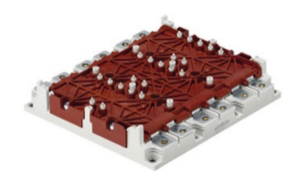
The application environment of electric vehicles imposes high safety requirements on electronic components. The motor controller uses Renesas’ SH72AW/AY microprocessor as the processing chip. The SH72AW/AY is a DSP chip designed for automotive-grade motor control. Its operating temperature range is -40°C to 125°C, and it embeds a special rotary encoder and decoder au6802. It can achieve multifunctional three complementary PWM or rectangular outputs from a pulse timer, two 16-bit timers, 160 m main frequency, and RISC (Reduced Instruction Set Computing). The IO power supply voltage is 5VDC. The motor controller uses SKiM93 IGBT power modules produced by Semikron. SKiM93 is a sintered semiconductor device that uses point-contact non-welding, as shown in the figure below. It utilizes AlCu bonding wires to connect diodes and high-performance thermal grease, improving its performance by 23%, with a fault-free temperature cycle reaching 1500 times.
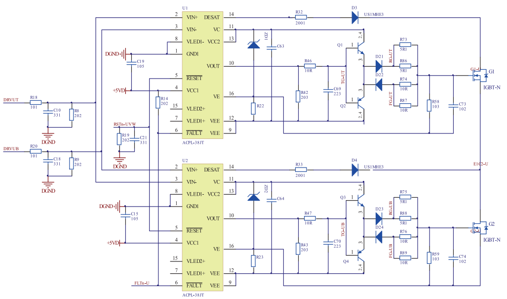
The motor winding drive circuit schematic composed of ACPL-38jt is shown in the figure below. To enhance the reliability of the drive circuit, a hysteresis undervoltage lockout circuit has been designed. When the power supply voltage falls below a certain value, an output hysteresis undervoltage signal is generated, and ACPL-38jt protects the IGBT based on this signal. To prevent both the upper and lower switches of the inverter bridge arm from turning on simultaneously, an input interlock circuit has been designed. To improve the driving capability of ACPL-38jt, a push-pull circuit is utilized. The output voltage is pushed and pulled through two fast transistors to increase the drive current, allowing for rapid driving of the 1200 V, 450 A IGBT module.
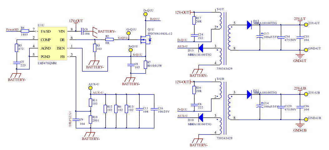
The motor controller uses three different power supplies: control board power supply, drive board power supply, and power module power supply. The control board and drive board are low voltage circuits, while the power module is a high voltage circuit, which generates significant impulse noise during switching, causing some interference to the low voltage circuit. To reduce interference between different power supplies, three different power supplies are provided to the corresponding circuits. Since the voltage levels of the control board and drive board are similar, one power supply can generate another power supply through an isolated power converter, as shown in the figure below. The isolated power converter can achieve isolation of weak electrical signals from the control board and strong current signals from the drive board, thereby enhancing the reliability of the system.
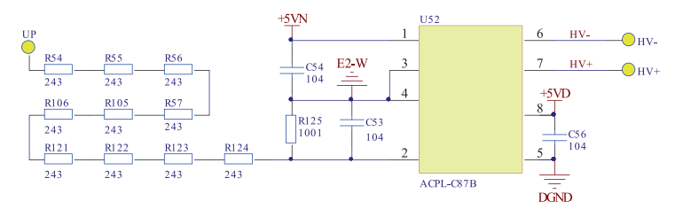
The permanent magnet synchronous motor controller needs to detect the three-phase winding current during coordinate transformation. There are two methods for current sampling: one is to detect the voltage across a precision resistor and then calculate the current according to Ohm’s law. This method is low cost, but the current flowing through the precision resistor generates some loss, and there is a temperature drift phenomenon at higher temperatures. This makes it suitable only for small current applications. The other method is to obtain the voltage signal directly through a current sensor. This method can measure large currents with low power consumption, and the current sensor is isolated from the windings. The downside of this method is the cost and size of the sensor. The motor controller usually measures two phase currents and then calculates the third phase current, thus requiring at least two current sensors. This motor controller uses LEM HC5F400S. The motor controller should monitor the bus voltage and current values in real-time to protect the motor under undervoltage, overvoltage, and overcurrent conditions. This motor controller uses a resistor divider method to measure the power bus voltage, and the voltage sensor uses Avago’s ACPL-C87, as shown in the figure below.
UP connects to the positive terminal of the power supply, and E2-W connects to the negative terminal. The sampling resistor is formed by ten 100 kΩ resistors and one 2 kΩ resistor in series.
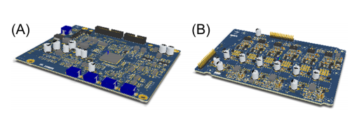
The PCB layout of the controller follows the principles of “first large then small, first difficult then easy, evenly distributed, balanced center of gravity, and aesthetically pleasing”, meaning that important unit circuits and core components should be arranged first. The layout of electronic components must refer to the main block diagram, and major components should be placed according to the signal flow direction. The power supply, driver chip ACPL-38jt, and push-pull circuit in the drive board are primary components to be placed first. The processor chip, sampling circuit, power circuit, and other minimum system circuits in the control board should be placed separately. At the same time, the electromagnetic compatibility (EMC) issues of the circuit board should be considered. The simplest way is to reduce the loop area of sensitive signals. The layouts of the controller board and the drive board are shown in the figure below.
All components of the motor controller have been certified for automotive applications, with a temperature characteristic range of -40°C to 125°C. Except for dual in-line pin headers and bus connectors, other components are packaged as surface mount devices (SMD). SMD components are small in size, lightweight, and easy to store. The size and weight of SMD components are only about 1/5 of traditional through-hole components. By adopting SMD technology, the size of electronic products is reduced by 40% to 60%, weight is reduced by 60% to 80%, vibration resistance is enhanced, and the defect rate of solder joints is low. Electronic products need to meet the EMC standards required by the application industry.
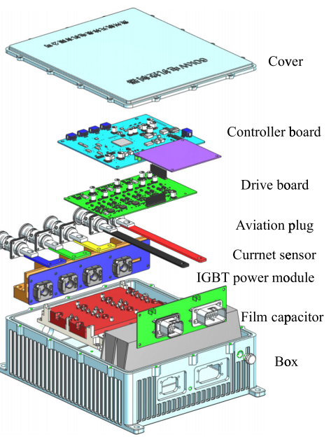
The electromagnetic compatibility model consists of three parts: interference sources, coupling paths, and sensitive devices. The interference sources in the motor controller include inherent noise, discharge noise, electromagnetic induction noise from components themselves, and noise generated by changes in voltage or current of semiconductor components during switching. The coupling paths of electromagnetic interference include conduction coupling and radiation coupling. In real life, all electronic products are subject to external electromagnetic interference, most of which is received through conduction coupling, with some received through radiation coupling. Methods to improve the electromagnetic compatibility of motor controllers are mainly divided into two categories: suppressing the emission of interference sources and cutting off or weakening the transmission energy of coupling paths. Methods to suppress interference source emissions include adjusting drive resistance, increasing RC absorption circuits, adjusting the switching frequency of power components, and reducing loops on the PCB. Methods to cut off coupling paths include shielding, grounding, and filtering. The motor controller uses an aluminum alloy shell and aviation connectors for shielding, and the shell is grounded. Its structure is shown in the figure below.
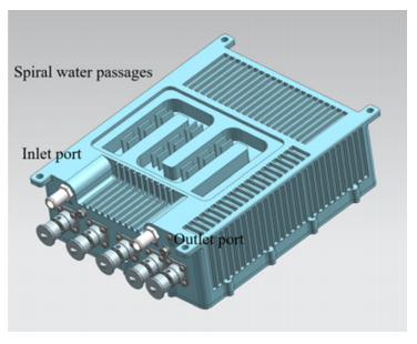
Electric vehicles require motors to have greater overload capacity. When the motor is overloaded, it usually leads to a significant temperature rise. To achieve higher overload capacity and power density, motor controllers typically use a spiral channel cooling method, as shown in the figure below.
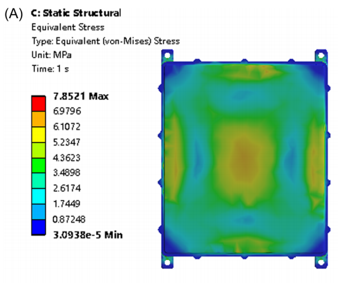
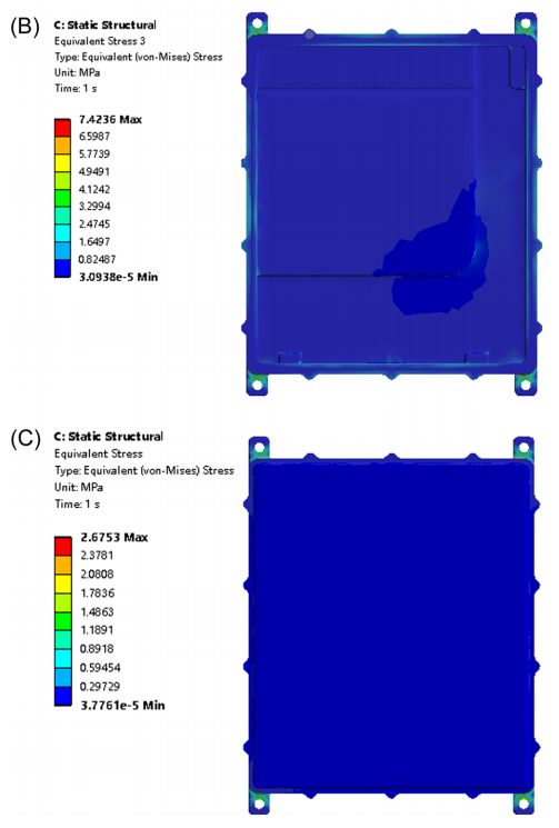
To reduce the weight of the motor controller, the casing and end cover are made of die-cast aluminum alloy YL113/ADC12, with a tensile strength of RM≥230 MPa. The design of the chassis and end cover is aimed at reducing local weight. However, the reduction of supporting materials may lead to a decrease in supporting capacity, so it is necessary to analyze the structural strength. Stress and deformation analysis of the cover plate, casing, and mounting ears are performed using the simulation module of UG software, as shown in the figure below.
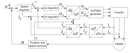
The principle of the PMSM controller is shown in the figure below. It consists of position sensors, coordinate transformation, SVPWM generator module, inverter, speed and current regulators.
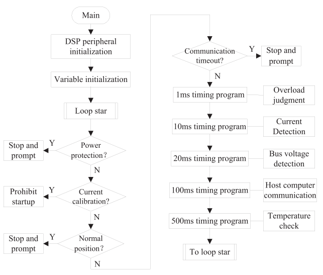
The software development environment for the motor controller is Renesas Electronics’ high-performance embedded workshop software. The entire program is divided into module function initialization programs, variable definition programs, main loop programs, and interrupt handling programs. The parameter initialization program completes the initialization of the relevant functional module registers, and the variable definition program completes the definition of variables and the setting of initial values. After initialization, the control program enters the main loop program. The flowchart of the main program is shown in the figure below.
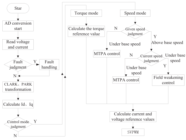
Renesas SH72AW/AY provides multiple interrupt resource entries, facilitating the implementation of various functions during the motor control process. Current and voltage sampling, coordinate transformation, space vector voltage output, maximum torque per ampere (MTPA) control, fault signal flag checking, fuzzy control calculations, etc., are all completed by the timer interrupts of the Event Manager. It is also the main interrupt program of the motor control program, as shown in the figure below.
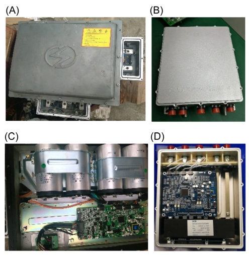
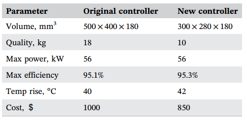
The motor control part adopts a modular structure. By pin splicing, there is no need for wiring between the modules. The controller has a neat appearance, making it easy to assemble and maintain. The IGBT module uses non-welding press-pin technology, which can reduce processing time. Rectangular film capacitors can effectively utilize the casing space, thereby reducing the size and weight of the casing. The controller terminal uses aviation connectors, which are very sturdy and secure. Aviation connectors facilitate worker operations, eliminating the need to open junction boxes and screw in screws. This saves raw materials, improves production efficiency, and reduces the cost of the motor controller. The size of the controller has been reduced to half of its original size, and its weight has decreased from 18 kg to 10 kg, making it more suitable for lightweight electric vehicles, as shown in the figure below.
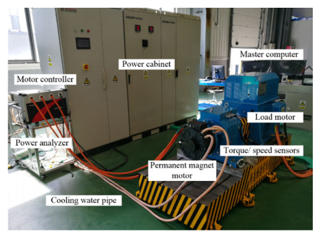
The motor and controller experimental platform is shown in the figure below.
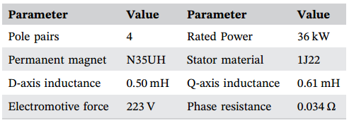
The power analyzer EV3000 has four measurement channels, one channel uses the single-instrument method to measure the DC bus voltage and current of the motor controller, and the other three channels use the three-instrument method to measure the voltage and current of the PMSM three-phase windings. Torque sensors and speed sensors measure output power. The measurement data is transmitted to the main controller via network cable, which displays the values and waveforms of the motor and controller parameters in real-time. Both the controller and the motor use external circulation water cooling. The parameters of the PMSM are shown in the table below.
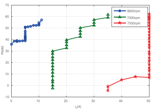
The maximum speed of the motor controller is 7500 rpm, and the rated speed of the PMSM is 6500 rpm. When the motor speed exceeds the reference speed (rated speed), the motor requires the weak magnetic field current provided by the controller. The figure below shows the application of magnetic flux weakening current (Id) at different powers (P) at 6600, 7000, and 7500 rpm.
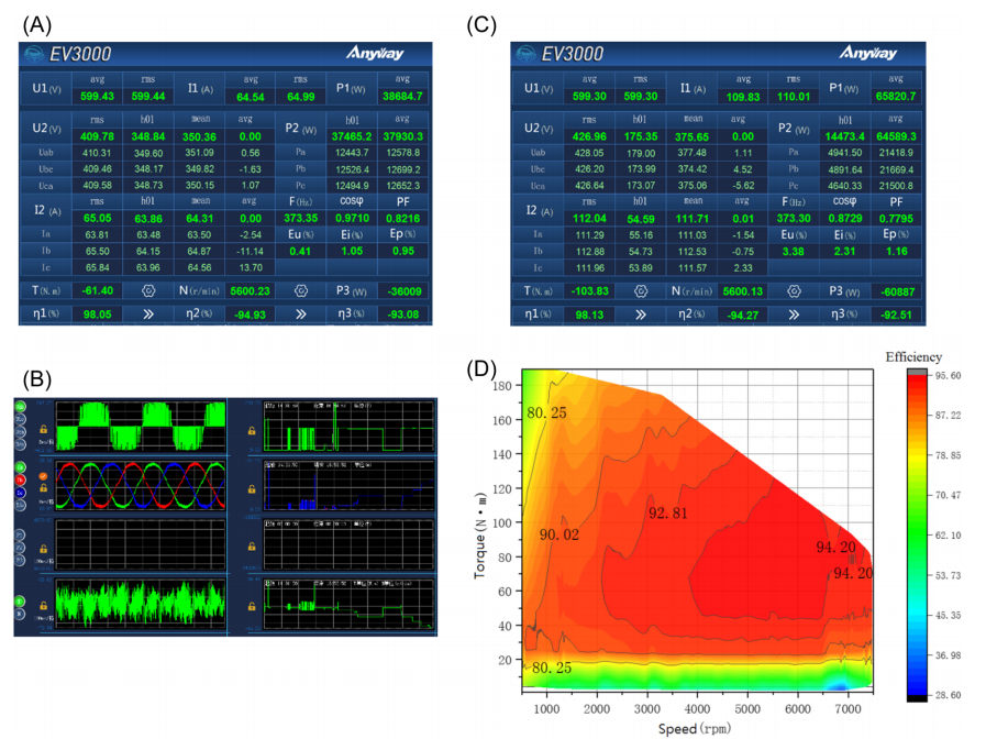
Figure A below shows the operating data of the PMSM and controller system at rated power (36 kW, 5600 rpm, 61 N·m). At this time, the efficiencies of the controller and motor are 98.05% and 94.93%, respectively, and the efficiency of the drive system is 93.08%. Figure B shows the output voltage, phase current, power, speed, and torque waveforms of the motor and controller. The right side of the figure is the response curve when the load changes. It can be seen that the overshoot of the drive system is small, and the response speed is fast. Figure C shows the performance of the PMSM controller when the maximum power reaches 60.8 kW, exceeding the designed peak of 56 kW, with the maximum efficiency of the controller being 95.13%. Figure D shows the efficiency map of the PMSM controller. The area where the controller efficiency exceeds 90% occupies two-thirds of the efficiency map.
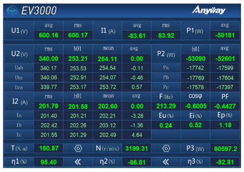
When the electric vehicle is going downhill or braking, the motor operates in generator mode. In the experiment, the permanent magnet synchronous motor is driven by an asynchronous motor to generate electrical energy. The figure shows the operating data when the generator peak power is 60.6 kW.
During the experiment, the input cooling water temperature was 30°C, and the water flow rate was 12 L/min. The motor operated under rated load (36 kW, 5600 rpm) for more than 1 hour. After the IGBT temperature rise stabilized, the maximum temperature rise was 42°C, meeting the design requirements. Then the input cooling water was controlled at 60°C, 12 L/min, resulting in an IGBT temperature rise of 45°C, with the maximum IGBT temperature being 105°C, below the junction temperature of 150°C. The comparison of the parameter performance between the original controller and the new controller is shown in the table below.
A 600 V/36 kW/5600 rpm permanent magnet synchronous motor controller has been designed for electric vehicles. To meet the requirements of small size, lightweight, wide speed range, and high power generation capacity for the permanent magnet synchronous motor controller, designs were made from three aspects: hardware circuits, structural components, and software algorithms. The use of surface mount components, film capacitors, and integrated power modules can effectively reduce the size of the controller. The spiral water cooling system ensures that the temperature rise of the controller is within the specified range. Hardware protection circuits and software protection algorithms together improve the reliability of the controller. The controller adopts a magnetic field weakening strategy to achieve a maximum speed of 7500 rpm for long-term operation. By adopting a modular design approach, the quality of the controller prototype has been reduced by 60%, and its volume has been halved, greatly improving production efficiency. An experimental platform for the motor and controller has been designed, and the three-phase winding voltage and current of the permanent magnet synchronous motor were measured using the power analyzer EV3000 with the three-instrument method. The experimental results verify the rationality of the design scheme. Currently, the parameters of the motor controller only apply to specific motors. After calibrating a certain motor, the parameters of the control characteristic curve can be written into the program, which is suitable for mass production models of motors, but it is relatively difficult for other models of motors. Motor parameter identification and adaptive control are the research directions for the next stage.
Statement:The content of this article is sourced from the internet. It is for sharing purposes only and does not represent the position of this account. If there is any infringement, please contact the editor for deletion. Thank you!