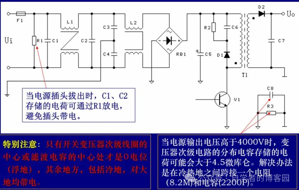
 01Electrical Clearance and Creepage DistanceIn high-voltage PCB design, specifically in switch mode power supply PCB design, attention must be paid to electrical clearance and creepage distance; insufficient spacing can lead to leakage.
General standards (which vary by industry, such as lighting, electric vehicles, etc.) require certified products: design according to standard tables.
GB4943.1 corresponds to EC60950.1 (IEC62368-1)
GB/T16935.1-2008 corresponds to IEC60664.1
IPC-2221
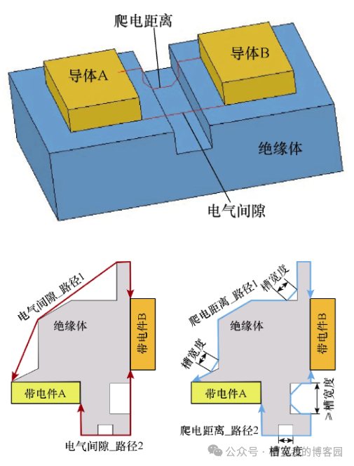
Electrical clearance and creepage distance in PCB design affect electrical performance, safety, and reliability.Electrical clearance and creepage distance are related to voltage, insulation materials (dielectric constant, arc resistance), temperature and humidity, pollution, and altitude.
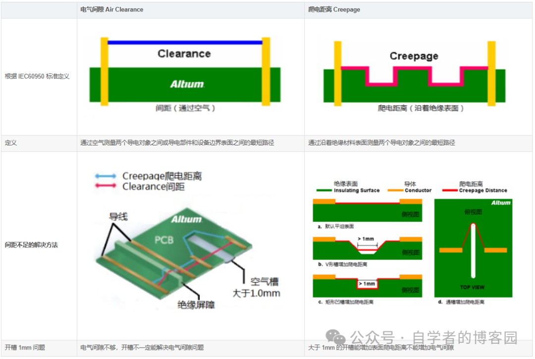
Solutions for Insufficient Electrical Clearance
1. Use insulating materials and, where possible, achieve spacing through double-sided assembly;
2. High and low voltage isolation, placing high voltage on top and low voltage on the bottom.
Solutions for Insufficient Creepage Distance
a. The diagram shows a flat surface; creepage distance is measured on the PCB surface between nodes;
b. The diagram shows a V-shaped groove that can increase the surface distance between nodes; the increased length is only measured along the groove, reducing to a point of 1mm width;
c. The diagram shows a rectangular groove that can further increase the surface distance, but the width must be 1mm or greater, which increases processing costs;
d. The diagram shows directly grooving the PCB; grooves greater than 1mm in width can hide surface distances, which is simple and practical.
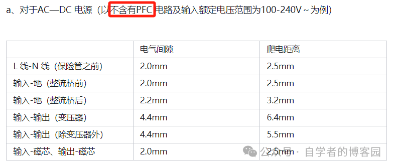
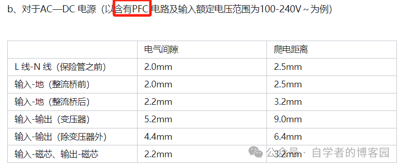
Reference for Electrical Isolation Distances of Electronic Components and PCBs
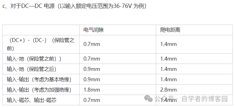
Reference for Electrical Isolation Distances Inside Transformers
The electrical isolation distance inside a transformer refers to the total width of the walls on both sides of the transformer. If the wall width of the transformer is 3mm, then the electrical isolation distance of the transformer is 6mm (the wall widths on both sides are the same). If the transformer has no walls, then the isolation distance equals the thickness of the insulating tape used. Additionally, for AC-DC power supplies, the primary and secondary windings of the transformer should use three layers of insulating tape for isolation, while for DC-DC power supplies, only two layers of insulating tape are needed.
The following values do not include margins:
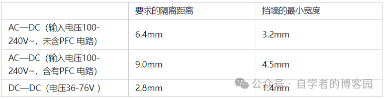
Note: If the transformer pins are not covered with insulating sleeves, the isolation distance at the pins may only be the thickness of the tape plus the wall thickness, so the transformer pins need to be covered with insulating sleeves that pass through the walls.
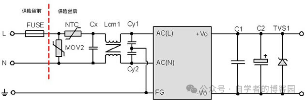
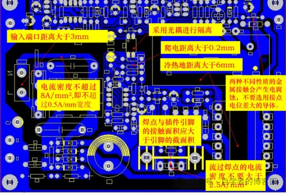
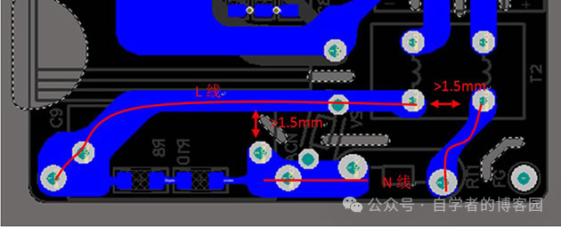 The electrical clearance between the L and N lines before the fuse = 2.0mm.
The electrical clearance between the L and N lines after the fuse = 1.5mm.
Conclusion on Electrical Clearance and Creepage Distance for 220V
Electrical clearance > 2mm
Creepage distance > 2.5mm
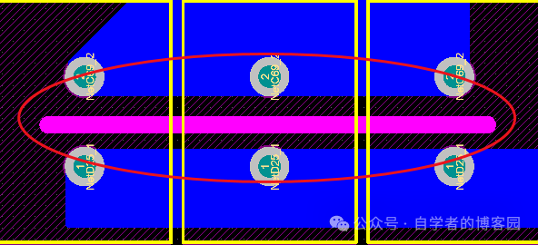
If encountering areas where creepage distance cannot be met, grooves > 1mm can be opened to meet design requirements and prevent leakage.
 02Electrical Clearance and Creepage DistanceTable Lookup
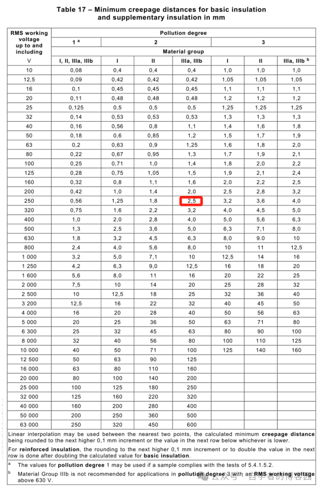
Reference IEC 62368-1-2018
Table Lookup Trilogy
① Confirm the minimum creepage distance, basic insulation and reinforced insulation, pollution level select 2, material level select IIIa and IIIb; if it is a 220V power supply, working voltage select 250V, the selected creepage distance is 2.5mm; here 2.5mm is basic insulation, reinforced insulation equals 2 times basic insulation, which is 5mm.
Reference IEC 62368-1-2018
② Find the transient voltage, select overvoltage category II, choose 300V
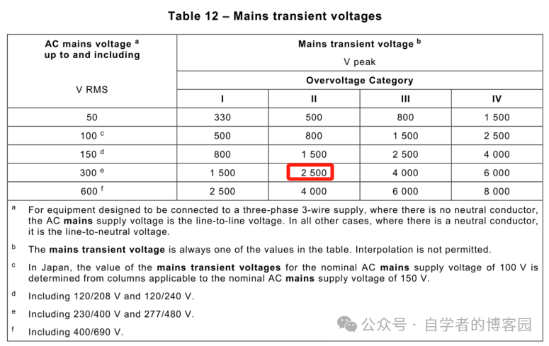
Reference IEC 62368-1-2018
③ Based on the transient voltage, query the electrical clearance; the electrical clearance based on insulation is 1.5mm, and the electrical clearance for reinforced insulation is 3mm.
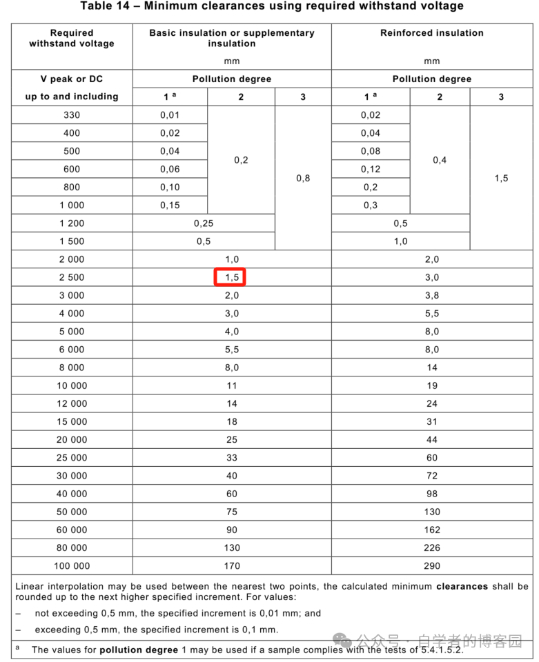
Reference IEC 62368-1-2018
Example Explanation
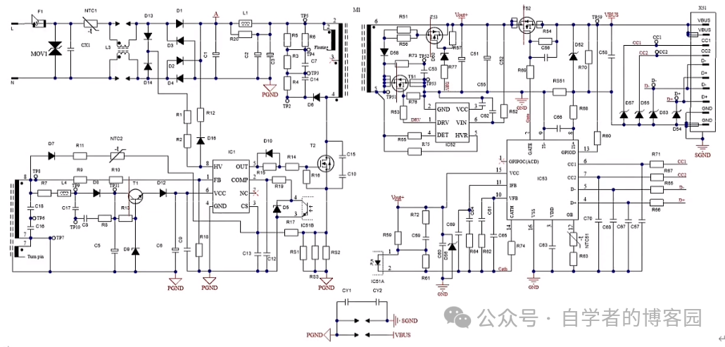
Conclusion (Input < 250V)
1. Before the transformer, the electrical clearance between L and N, and the electrical clearance before and after the fuse is 2mm + 0.2mm (error), creepage distance is 2.5mm + 0.2mm (error).
2. The electrical clearance between the primary and secondary of the transformer is 4.6mm, and the creepage distance is 6.4mm. (If the creepage distance is insufficient, open grooves > 1mm in width).
Copyright Statement: This article is an original work by CSDN blogger “Lao Qin and Liang Thinking”, following the CC 4.0 BY-SA copyright agreement. Please include the original source link and this statement when reprinting.
Original link: https://blog.csdn.net/joeqinyu/article/details/136240789

This account maintains neutrality regarding all original and reprinted articles’ statements and viewpoints. The articles are provided for readers’ learning and communication. The copyrights of articles, images, etc., belong to the original authors. If there is any infringement, please contact for deletion.