Hello everyone, I am Pi Zi Heng, a serious technical person. Today, I will introduce to you the impact of the RESET# pin of the i.MXRT1064 internal Flash on program startup and operation.
In the previous article “The Abnormal Programming Caused by the Loss of SFDP Table in i.MXRT1024/1064 Internal 4MB Flash”, I provided a preliminary understanding of the 4MB Flash integrated on the i.MXRT. Generally speaking, using integrated Flash is more convenient than using external Flash, but this is only true if you fully understand its integration method, signal connections, and other details. If you do not fully grasp these details, the integration can be like a black box, and it may not be more reliable than using external Flash.
Recently, another RT1064 customer reported that their product experiences a very low probability of crashing during operation. Analysis revealed that during the crash (under power), the program data read back from the internal Flash was all 0x00, suggesting that the Flash content had been tampered with. However, after a power cycle, it worked normally again. What is going on? Today, I will discuss this topic with you:
- Note: The issues described in this article only occur on the RT1064 and do not exist on the RT1024.
1. Differences in Internal Flash Connections of RT1024/1064
1.1 Different Packages of W25Q32JV
We know that the internal integrated Flash of RT1024/RT1064 is the Winbond W25Q32JV bare die. When sold as a standalone product, the W25Q32JV actually offers a variety of package forms, the most familiar being the classic 8-pin SOIC-8 208-mil package.
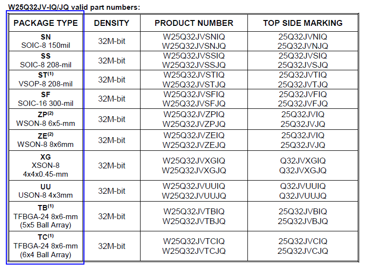
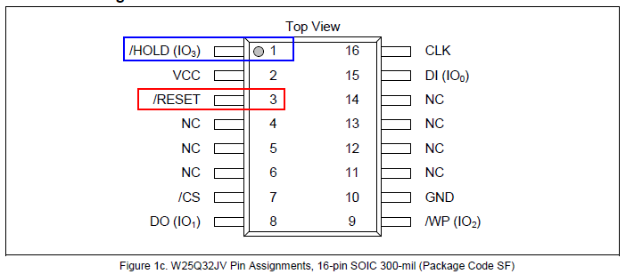
From the perspective of the W25Q32JV bare die, it has a total of 9 signal lines. In the SOIC-8 package, the RESET# signal, which should be separately routed, is multiplexed onto IO3 (although this pin also has a HOLD# multiplexed). In the SOIC-16 or TFBGA-24 packages, we can see the separate RESET# signal:
1.2 RESET# Connection on RT1024
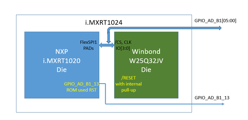
On the RT1024, the RESET# signal of the internal Flash is left floating (or handled otherwise) and is not connected to the RT1020. Here, GPIO_AD_B1_13 is emphasized because the RT1024 BootROM will control this I/O to reset the Flash based on the efuse configuration (which is evidently ineffective).
1.3 RESET# Connection on RT1064
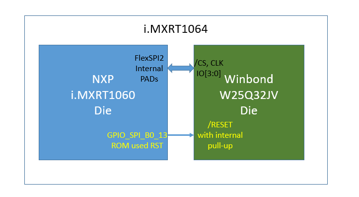
On the RT1064, the RESET# signal of the internal Flash is connected to the internal signal GPIO_SPI_B0_13 of the RT1060. Of course, the RT1064 BootROM will also control this I/O to reset the Flash based on the efuse configuration (which will have a certain effect).
2. Risks of Not Handling the Internal Flash RESET# Signal
In my previous article “In-depth Analysis of the Serial NOR Flash Startup Initialization Process in the i.MXRT Series”, in section 2.1 Resetting the Flash Chip, we learned that if the RESET# related bits in the efuse are enabled, the RT1064 BootROM will initialize the GPIO_SPI_B0_13 pin to GPIO output mode and pull it low and high once to reset the Flash. After the reset, GPIO_SPI_B0_13 will maintain a high output level.
// RESET# related fuses on RT1064
fuse 0x6e0[7]  - FLEXSPI_RESET_PIN_EN
        0 - Disable
        1 - Enable

fuse 0x6e0[31] - FLEXSPI_RESET_PIN_SEL
        0 - GPIO_SPI_B0_00
        1 - GPIO_SPI_B0_13
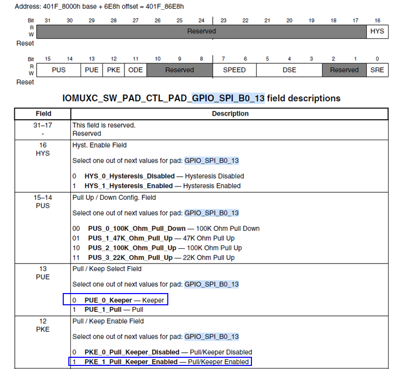
However, by default, neither the RT1064 chip nor the customer will program the efuse related to this RESET#, which means that the internal pin GPIO_SPI_B0_13 will always remain in its power-up default state. So what is the default state? This can be inferred from the default value of the IOMUXC_SW_PAD_CTL_PAD_GPIO_SPI_B0_13 register, which is 0x10B0, indicating it is in input keeper state.
We know that the RESET# signal is also an input for the Flash (as learned from Winbond technical personnel, this signal has a 280K ohm pull-up internally). With both pins connected and both in input state, it is evidently not very reliable. In an extreme case, during the power-up process of the chip, if the weak pull-up on the Flash side causes the voltage to rise to an effective high level (VCC x 0.7) before the GPIO_SPI_B0_13 input keeper state takes effect, it will create a weak pull-down. Due to the differences in device characteristics among different chips, both the weak pull-up and pull-down have a certain error range, which may ultimately lead to the RESET# level being in an indeterminate state. Furthermore, even if there are no issues during the power-up process, in actual operation, various factors such as internal temperature and electromagnetic environment can cause the RESET# signal to flip, which would be devastating to the stability of XIP program execution.
3. Solutions for Stabilizing the RESET# Signal
To verify the impact of the GPIO_SPI_B0_13 signal state on the RT1064, I added control of this signal in the SFDP test project. When GPIO_SPI_B0_13 outputs low, the Flash RESET# is in an active state, and at this time, the Flash SFDP cannot be read normally, let alone memory data read operations.
- Burn SFDP project: https://github.com/JayHeng/func-imxrt-sip-flash-sfdp-check
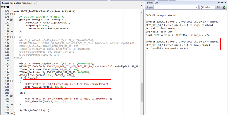
So, how can we solve this problem? After understanding the above principles, the solution is actually quite simple:
- To solve the startup issue: Program the two bits of fuse 0x6e0[31,7] to let the BootROM initialize the GPIO_SPI_B0_13 pin. (This will increase the startup time by about 750us)
- To solve the runaway issue: If the chip has no startup issues but you do not want to program the fuse, then the first thing the XIP App should do after starting is to initialize GPIO_SPI_B0_13 to GPIO output mode and set it to high. (For reliability, this part of the code can run in RAMFUNC)
Thus, failing to handle the RESET# pin of the i.MXRT1064 internal Flash may lead to startup failures or program runaway. This concludes my introduction, where are the applause~~~

END
Source: Pi Zi Heng Embedded
Copyright belongs to the original author. If there is any infringement, please contact for deletion..▍Recommended ReadingHow much does a genuine Keil cost?Microcontrollers can output PWM like thisSharing an embedded development debugging tool!→ Follow for more updates ←