Note that there are three essential conditions that must be met:
The first is that the shape, size, and pin diameter and length of the plug and socket must correspond one-to-one; otherwise, the connection operation cannot be completed. This stipulates the physical structure and pin definition of the plug combination.
The second is that the output voltage of the power supply must meet the demand value on the load side; otherwise, the electrical parameter requirements cannot be fulfilled. This determines the voltage specification of the plug combination.
The third is that the output impedance of the power supply must match the input impedance of the load; otherwise, perfect power supply cannot be achieved. This determines the working characteristics of the power supply.
These three points are essentially the normative protocol of the power supply plug combination on the physical layer.
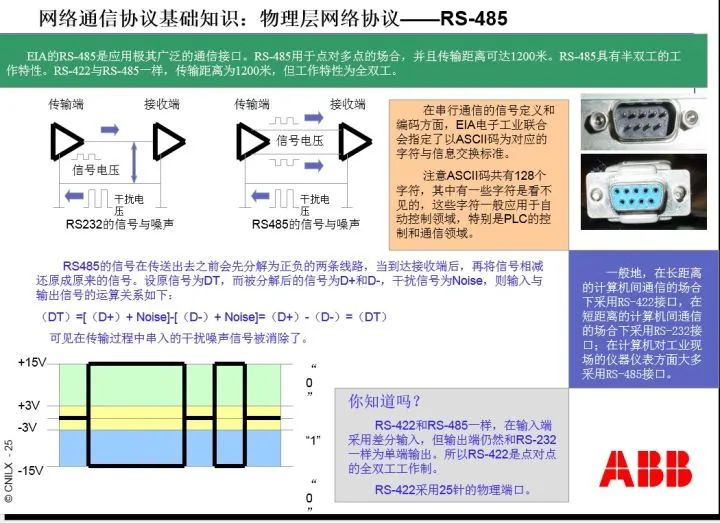
Now let’s look at communication interfaces. In the ISO/OSI model concerning computer information exchange, the physical layer is the lowest layer (the first layer), which stipulates the mechanical shape of the interface, pin definitions, interface levels, and byte formats.
The byte format here refers to how many data bits are in one byte, how many start/stop bits there are, and how many parity bits there are. Generally, one byte has 8 data bits, 1 start bit (stop bit), and 1 parity bit. Note: Start and stop bits can be combined.
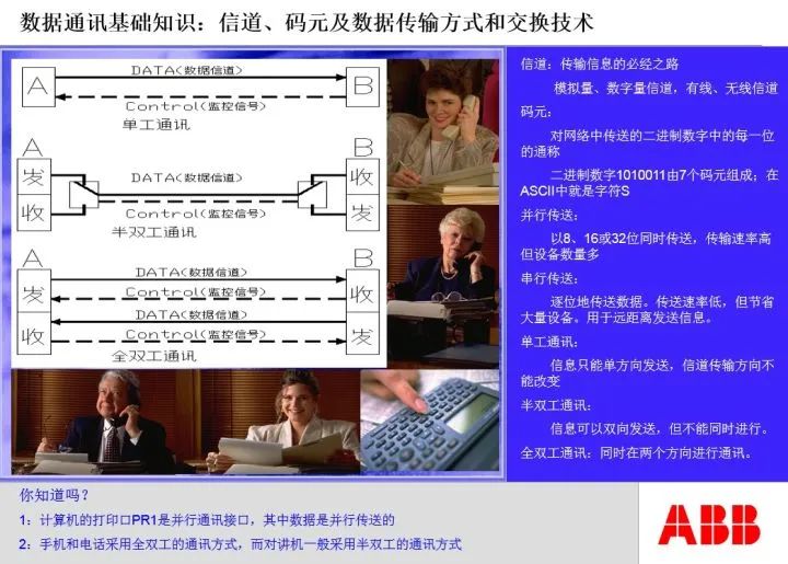
Next, let’s look at the working mode of communication interfaces and networks.
When we make a phone call, we find that both parties can talk and listen simultaneously; this is called full duplex (two-way working mode); if you cannot listen while speaking, and cannot speak while listening, but either party has the ability to speak and listen, which is the intercom communication style, this is called half duplex.
(To explain: These images are excerpts from a PPT on MODBUS communication made by the author at ABB, which is relatively old, but the basic content is correct. These images are for reference.)
RS422 and RS232 interfaces are full duplex interfaces, while RS485 is a half duplex interface.
For half duplex interfaces, there must be a communication initiator; thus, RS485 interfaces and networks must have a master station and several slave stations, and the number of slave stations is also specified. Generally, the number of slave stations is 32.
The relationship between the RS485 master station and slave stations seems to be just a difference in communication working modes, but its essence is the reasonable allocation of control rights over the communication bus among all parties involved in the communication.
Now let’s look at bus connection issues.
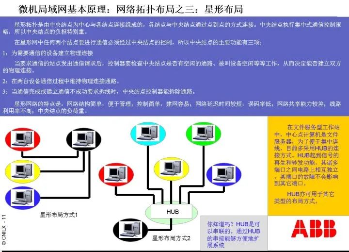
Still taking the power supply as an example. We can draw a main line from the power supply and then parallel several branches to send to various loads. As long as the power supply’s power requirements are met, this is evidently feasible.
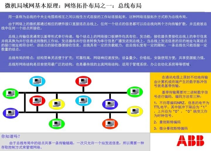
If we use the same method to draw the RS485 communication line, is it feasible? The answer is no. We must first draw a line from the communication master station to the first communication slave station, then draw a second line from the first slave station to the second slave station, and so on until the last slave station. At the end of the communication line, a terminal resistor must also be added. If any point on this communication line experiences a disconnection, the communication on the subsequent communication links will also be interrupted. This wiring method is vividly called the daisy chain connection method or chain connection method, while the power supply connection method is called the star connection method.
We find that from an electrical wiring perspective, the links are parallel. However, from a communication perspective, the links are daisy-chained, representing an orderly connection one after the other.
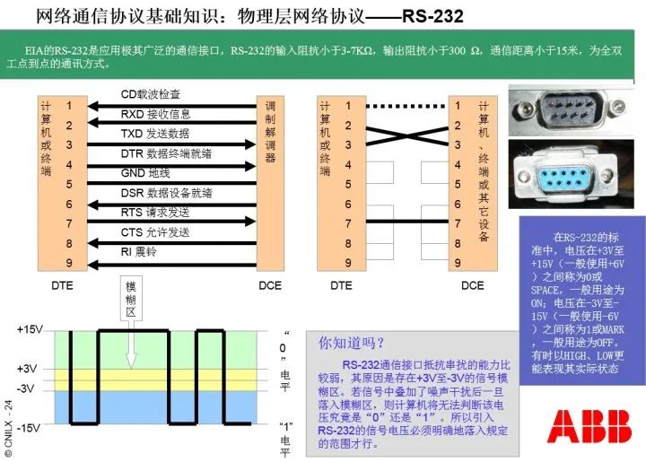
The wiring method for the RS485 bus network must be a daisy chain connection method and belongs to half duplex communication; RS232 is a point-to-point wiring method and belongs to full duplex communication. Whether it is the RS232 interface or the RS485 interface, they must comply with the communication protocol of the physical layer.
Now let’s look at the MODBUS-RTU communication protocol:
Having a physical layer communication interface, does that mean communication can occur? The answer is no. The physical layer communication interface only provides the conditions for communication between both parties. However, if neither party can understand what the other is saying, or if the speaking methods and grammatical structures of both parties do not match, communication cannot occur.
In the OSI model, above the physical layer is the data link layer. The MODBUS-RTU protocol is a data link layer protocol; as long as both parties adopt the MODBUS-RTU protocol, it ensures that the communication language is in a format both can understand.
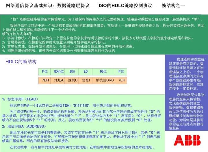
Note the term “statement” here. The physical layer defines bytes, which are equivalent to words in a language, while the data link layer organizes bytes into statements, or frames. Frames specify the grammatical structure of the statements used by both parties in communication.
MODBUS is also master-slave structured. Just like the bus control at the physical layer, the master-slave relationship here specifies the control rights over the communication bus. The master station first issues a command, occupying the bus; then it vacates the bus for the slave station to write a response code; after the slave station completes its task, it returns the bus to the master station.
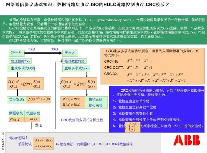
Now let’s take a look at the frame structure defined by ISO’s HDLC, which is the grammatical structure of communication statements, as follows:
Under the MODBUS communication protocol, different command function codes have different frame structures. For the read register command, the frame structure of the MODBUS master station is: 2 bytes of address code, 1 byte of function code, 2 bytes of data address code, and 2 bytes of CRC check code; the frame structure of the MODBUS slave response is: 2 bytes of function code, 1 byte of the total number of response area bytes, N bytes of response data, and 2 bytes of CRC check code.
Although the physical layer protocol and data link layer protocol are different, the execution of the data link layer protocol must be based on the fact that the physical layer connections between both parties meet the requirements and can facilitate unobstructed information exchange.
This rule must be fully and thoroughly implemented in the ISO/OSI model’s seven-layer protocol. In the ISO/OSI model, the lower-level protocols of both parties must establish a transparent and fault-free connection and information exchange relationship for the upper-level protocols. In other words, the hierarchical relationship between levels must be absolute.
From the data link layer upwards, it is the network layer. Its task is to form the information exchange network of the field bus.
The functions of the network layer include: packaging communication frames into data packets and then sending the data packets to the other party.
Since the network structures of both parties may differ, the same type of network requires a bridge for connection, while different types of networks require a gateway for connection.
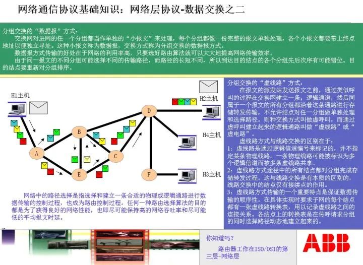
There may be multiple channels between networks. Data packets have multiple paths to choose from when being sent. The component responsible for selecting the path is called a router. The router not only determines the actual data exchange network path but can also construct virtual network paths and decide the sending order of data packets. Therefore, the router is the most complex and critical equipment in the network layer.
In the OSI model, the physical layer + data link layer + network layer is collectively referred to as the field bus, with its communication interface being the 8-pin RJ45 crystal head. It is evident that RJ45 is entirely different from RS232/RS485/RA422.
The data packets of the network layer are combinations of data frames. In simple terms, a data packet is a short article or a page of data combination unit to be transmitted.
The network layer, when sending data packets, has routing issues and reception combination issues as shown in the following images:
We see that the network layer first determines the routing path via the router during communication, and then sends the packets to the other party. Upon receiving the packets, the other party combines them in the order they were sent, then unpacks them into the actual document.
It is worth noting that: because the network layer has routers, the network layer supports star network structures.
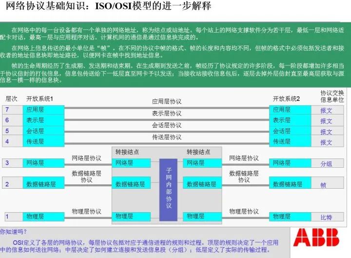
Now let’s focus on the ISO/OSI 7-layer model as follows:
It should be clear that from the network layer upwards, the information units sent between layers are already complete messages. The OSI model also stipulates the grammatical structure of messages, which is omitted here due to space constraints.
It is noteworthy that: the communication interfaces of RS232/RS485/RS422 and their definitions are very clear. This includes the voltage levels of the pins, the functional definitions of the pins, and the data flow timing relationships during information transmission and reception at the interface, all of which must be accurate and strict; otherwise, information exchange cannot be executed.
When a PLC exchanges information with a certain power meter, and these power meters comply with the RS485/MODBUS-RTU communication specifications, what should we do?
First, wire according to the daisy chain structure communication link requirements, connecting the PLC’s communication interface with the N power meter interfaces. The last power meter’s end must be equipped with a 100-ohm terminal resistor.
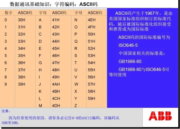
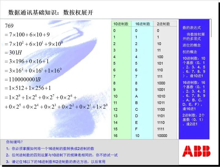
Second, determine each power meter’s address according to the incrementing principle, such as 01H, 02H, 1FH, etc. Here, H indicates hexadecimal, and 1F represents 16+15=31.
Third, set the communication rate specified for the power meters in the PLC programming software.
Fourth, in the PLC programming software, set the MODBUS communication code according to the data area address code of the power meters, as well as the cyclic relationships of each slave station.
Note that the MODBUS communication code here meets the requirements of PLC’s IEC 61131-3 programming module, while general PLC ladder diagrams do not have this function. The ladder diagram meets the requirements of IEC 61131-1 but does not meet those of IEC 61131-3.
Fifth, allocate a dedicated data area in the PLC’s memory to store the information read from the power meters and processed, so that the higher-level master station can read the information. This data area is called a data point table, sometimes also referred to as a communication protocol.
Finally, of course, there is the boot test. There is a lot of content involved, and it will not be introduced further due to space constraints.
Let’s look at an example of reading data using MODBUS-RTU on an RS485 network:
For a power meter with address 01H, there are six data points such as three-phase current and three-phase voltage stored at position 2000 in the power meter’s memory, with each data point occupying two bytes, totaling 12 bytes.
The communication rate of this power meter is 9600 bps. What does this mean? Bps indicates one 0/1, which is a bit, meaning that 9600 bits can be sent on this bus every second. We already know that one byte has 8 data bits, 1 start bit, and 1 parity bit, totaling 10 bits, so if the power meter’s communication rate is 9600 bps, then 960 bytes can be sent in one second: 9600/10=960 bytes.
We also know that the frame structure of the master station’s read data (downstream frame) includes 1 byte of address, 1 byte of function code, 2 bytes of memory address, 2 bytes of data quantity, and 2 bytes of CRC check code, totaling 8 bytes. Therefore, the time occupied by the master station sending the read data MODBUS communication frame is: 8X10/9600=8.33 milliseconds.
For this example, we know that the MODBUS-RTU read data command is 0X03H, which is the 03 command. Note the writing here: 0X is the prefix, 03 is the command, and H indicates hexadecimal.
The specific communication frame is: 01 03 07 D0 00 06 C5 45, where 0X01H is the address, 0X03H is the command, 0X07D0H is the memory address 2000, 0X0006H indicates reading six consecutive words, which are the current and voltage parameters in memory, and 0XC545H is the CRC check code for 01 03 07 D0 00 06.
The response frame from the power meter (upstream frame) has the following frame structure: 1 byte of address, 1 byte of function code, 1 byte of data area byte count, 12 bytes of data, and 2 bytes of CRC check code, totaling 17 bytes, occupying a time of: 17X10/9600=17.7 milliseconds.
The specific response communication frame from the meter is: 01 03 0C 00 64 0064 0064 00 DC 00 DC 00 DC D6 F5, where 0X01H and 0X03H have the same meanings as before, 0X0CH indicates that there are 12 bytes in the upload data area, 0X0064H indicates that phase A current is 100A, the following two groups are phase B and C currents, both 100A, 0X00DCH indicates that phase A voltage is 220V, and the following two groups are phase B and C voltages, both 220V, with 0XD6F5H being the CRC check code.
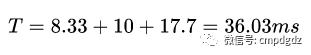
After the master station initiates the downstream communication frame, it waits 10 milliseconds for the slave station to respond, and then receives the upstream communication frame returned by the slave station, totaling:
If there are 31 identical meters waiting for the master station to access one by one, then the total time from when the master station starts accessing the first meter to when it finishes responding to the last one is:
Here, 1.12 seconds is the reading data cycle for these 31 meters at a communication rate of 9600 bps, and neglecting the wait time for the master station to send the downstream communication frame again, the actual time will be slightly longer.
I believe that after seeing this, everyone should have a deeper understanding of the communication frames under MODBUS-RTU.
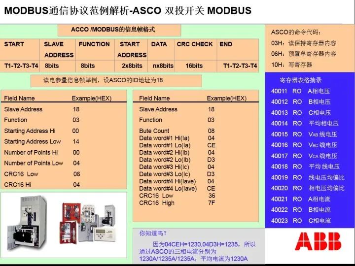
Reminder: A word consists of two bytes. Generally, a byte can only express 8 binary states. However, for analog quantities, it must be expressed using words. For example, a current of 1250A is expressed as 04E2H in hexadecimal, requiring 2 bytes for complete expression. Therefore, various power meters express analog quantities using words.
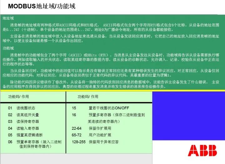
The following are some commonly used function codes in MODBUS, i.e., command codes:
Below are examples of the downstream and upstream communication frames for the PLC in reading the data point table of the ASCO controller:
Let’s clarify a few related questions:
1) Some field buses use tokens to solve the control rights issue of the bus.
It is easy to think that if a slave station has an urgent matter requiring service from the master station, but MODBUS stipulates polling rules, waiting for its turn may be too late. Therefore, many field buses have invented a special thing called a token. A token is short, only one byte, and can be quickly passed on the bus. The token is passed among stations; whoever gets the token becomes the master station and can publish information. If the station has nothing to publish, it passes the token to the next station, thus solving the bus occupation issue.
2) When a link experiences disconnection, to avoid communication interruption, a dual master station measure can be adopted.
The two master stations (PLC’s two master station RS485 interfaces) are connected by a handshake line. Normally, the primary RS485 is active while the auxiliary RS485 is floating. The floating RS485, although connected to the bus, is in a high-resistance state equivalent to complete disconnection. When a disconnection occurs, the slave station confirms and immediately activates communication, connecting from both ends of the link.