▼ Follow our official account:Engineers Look at the Sea ▼
This article is from the fourth generation apprentice of Look at the Sea: XJIE
https://blog.csdn.net/NANY_ying?type=blog
https://github.com/xiaojie25
Hello everyone, this document is designed to help you quickly get started with the implementation of digital filters on microcontrollers. Of course, after reading, you may still have some questions, and you can look up the information yourself.
In the last lesson, we implemented a frequency counter function on the STM32F103C8T6, and we will proceed with the next steps based on that.
First, digital filters are divided into FIR and IIR types (if you don’t understand, you need to look up the information). Here, we are concerned with how to obtain the parameters of the filter we want.
We open MATLAB.
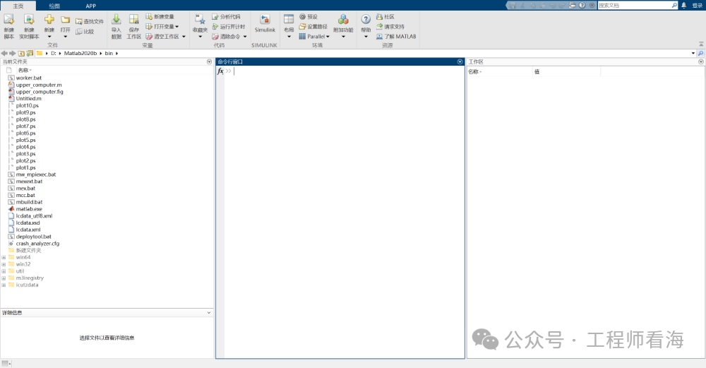
In the command window, type filterDesigner.
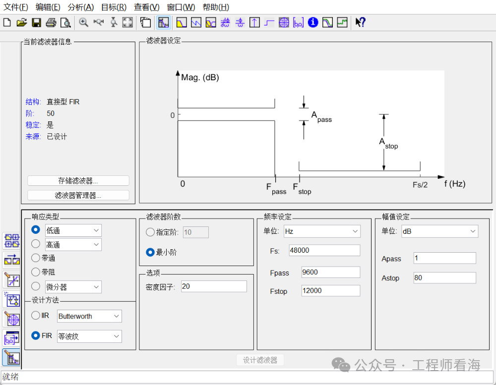
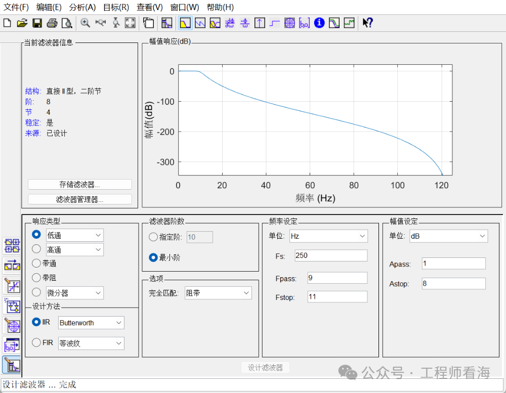
I want to design an IIR low-pass filter with a cutoff frequency of 10Hz, Butterworth type. The sampling frequency here needs to be consistent with the ADC sampling frequency we designed in class (250Hz).
This filter designer has many functions, which I leave for everyone to explore.
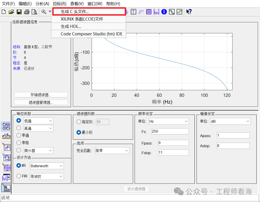
Click on Target -> Generate C Header File in sequence.
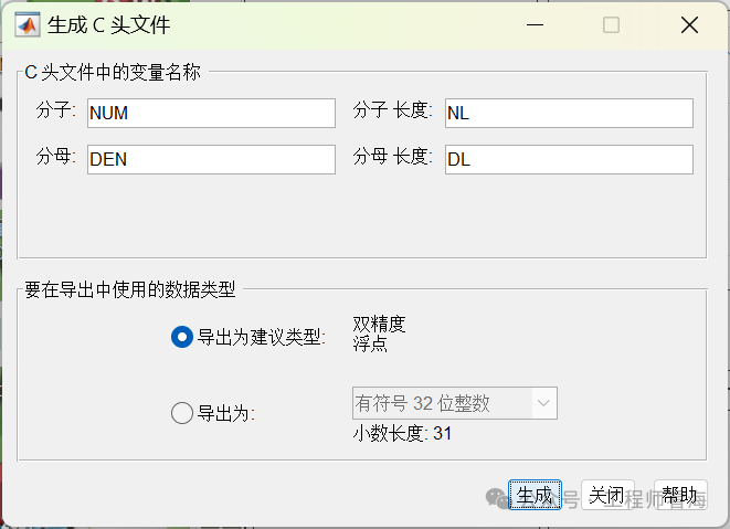
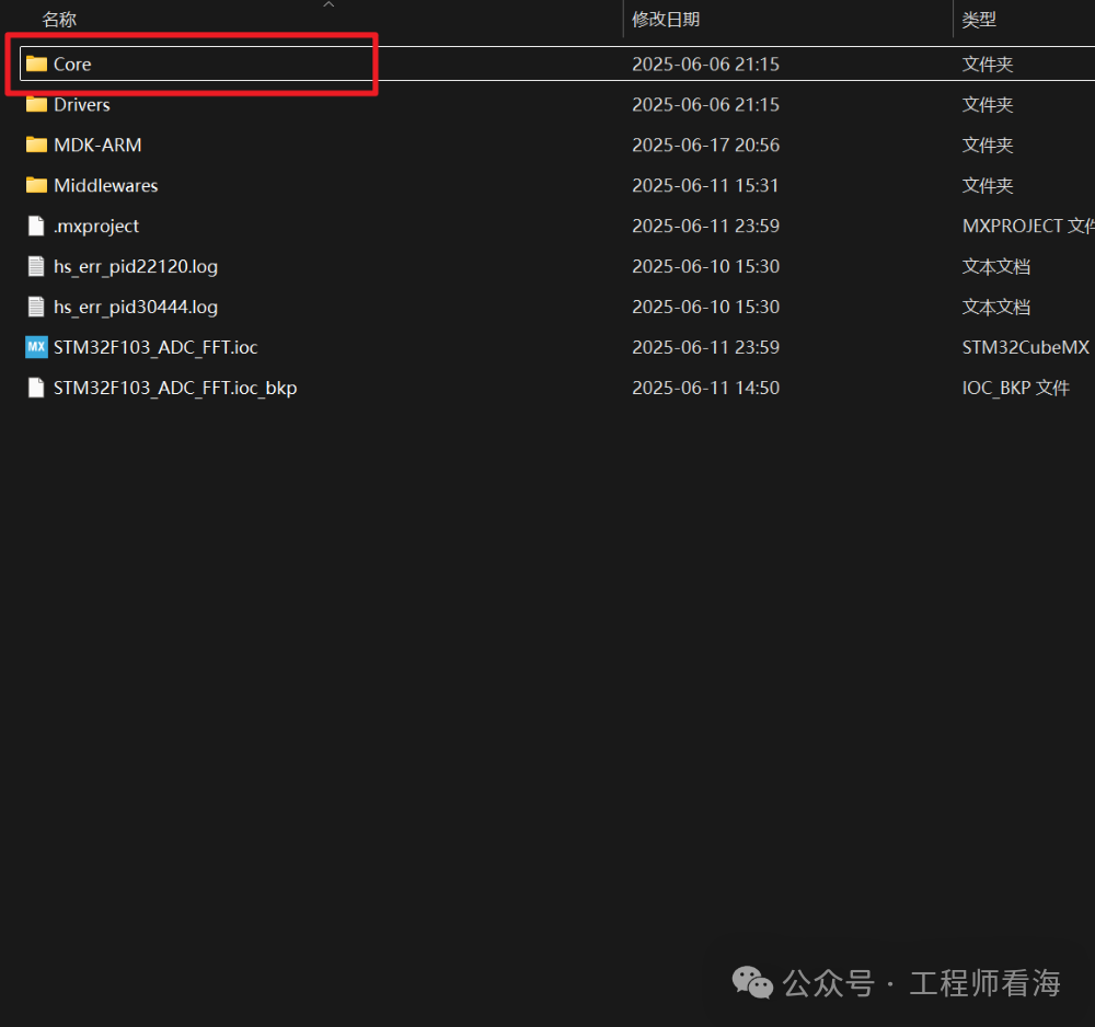
Click Generate directly (remember where you saved it), then we find the .ioc file generated by STM32CubeMX, and save the generated file in the folder as shown in the figure.
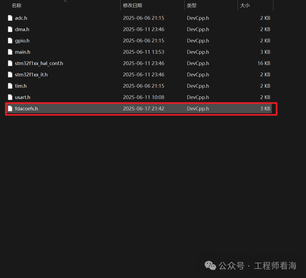
We open the fdacoefs.h file with Notepad, which will tell us that we need to add another .h file.
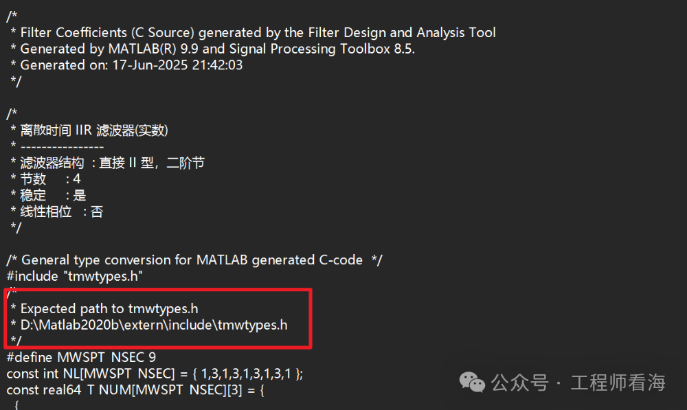
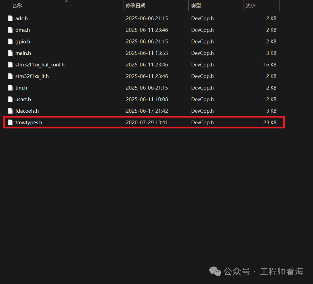
We find this file and also copy it to this folder.
At this point, the basic parameter generation and file movement are complete. Next, we start the code operation.
(This article is from the fourth generation apprentice of Look at the Sea: XJIE
https://blog.csdn.net/NANY_ying?type=blog
https://github.com/xiaojie25)
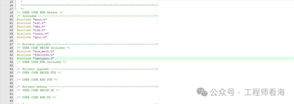
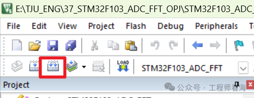
In main.c, include the two files we just added. Then compile this project.
Right-click on the fdacoefs.h file. Open it.
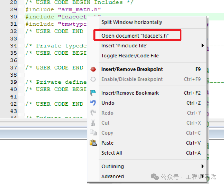
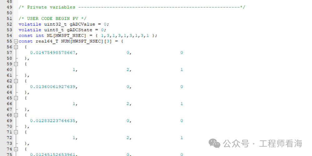
We cut the four arrays inside to main.c.
We first define two structures to record the parameters of our filter.
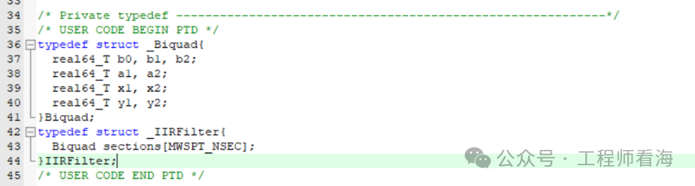
Among them, Biquad is the parameters of each section (knowledge of digital filters), and IIRFilter is the structure of the entire filter. Then we write these two functions in appropriate places in the code.
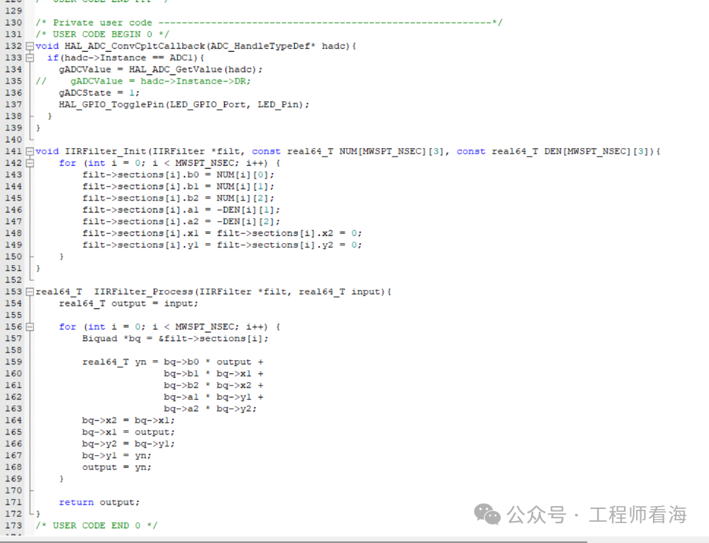
IIRFilter_Init is for initializing the filter, which fills the parameters we just generated into our defined filter,
IIRFilter_Process is for filtering the data when it comes in.
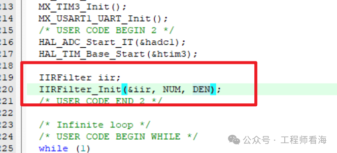
First, define an IIR filter and initialize it.
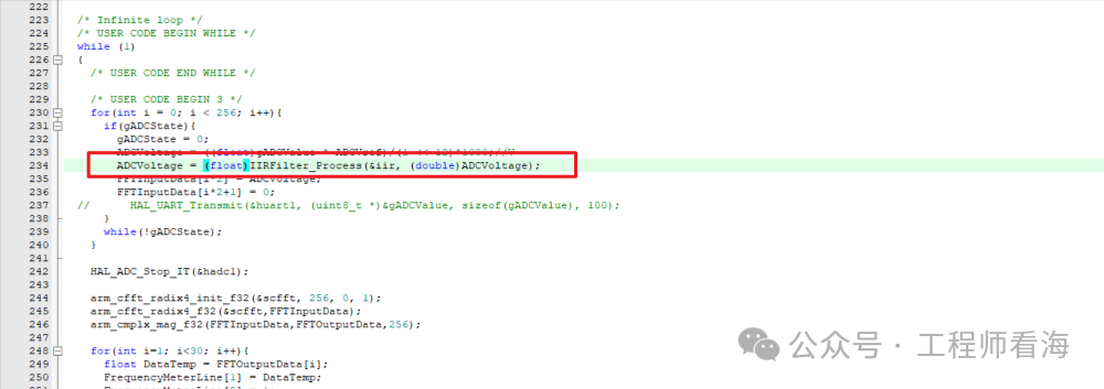
We filter the voltage collected by the ADC through the filter, let’s see the effect!
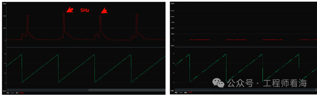
On the left, I have a 5Hz signal, and on the right, a 15Hz signal, both at 100mVpp. Since the cutoff frequency of the low-pass filter is 10Hz, the 5Hz signal passes through the filter while the 15Hz signal is attenuated by the filter.
By the way, the entire code may not be easy to understand for beginners; this is a challenge and an opportunity for you.
This article is from the fourth generation apprentice of Look at the Sea: XJIE
https://blog.csdn.net/NANY_ying?type=blog
https://github.com/xiaojie25
More learning content on Multisim and operational amplifiers!
All in “Operational Amplifier Secrets”

【Taobao】https://e.tb.cn/h.hchV7elOIgvyGd8?tk=QEVgVt9nBw6 CZ321 “Operational Amplifier Secrets Volume 1_Operational Amplifier Multisim Simulation Course_Engineer Look at the Sea Operational Amplifier Tutorial”
Click the link to open directly or search on Taobao to open directly.