The STM32 microcontroller, based on the ARM Cortex-M3 architecture, has a complex and efficient internal bus structure that supports the entire system’s data flow and instruction execution, making it a key learning point for many embedded engineers. Below, we will list the main internal buses of the STM32 microcontroller and their functions.
1. I-Code Bus
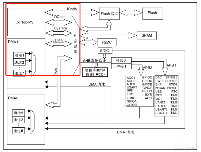
Type: Instruction Bus Protocol: Based on AHB-Lite Bus Protocol Width: 32 bits Function: Connects the Cortex™-M3 core’s instruction bus to the flash instruction interface, responsible for fetching instructions within a specific memory address range (0x0000_0000 to 0x1FFF_FFFF). The CPU core can fetch two 16-bit Thumb instructions at a time.
2. D-Code Bus
Type: Data Bus Protocol: Based on AHB-Lite Bus Protocol Width: 32 bits Function: Connects the Cortex™-M3 core’s data bus to the flash memory’s data interface, responsible for data access operations within the same memory address range. It supports data constants and debug access, and only supports aligned access of AHB-Lite.
3. Type Bus
Type: Peripheral Bus Function: Connects the Cortex™-M3 core’s system bus (peripheral bus) to the bus matrix, coordinating access between the core and DMA. Responsible for all data transfers within a specific address range (0x2000_0000 to 0xDFFF_FFFF and 0xE010_0000 to 0xFFFF_FFFF), including instruction fetching and data access.
4. DMA Bus
Function: Connects the DMA’s AHB master interface with the bus matrix, coordinating access from the CPU’s D-Code and DMA to SRAM, flash, and peripherals. DMA provides high-speed data transfer, reducing the CPU’s load.
5. Bus Matrix
Function: Coordinates access arbitration between the core system bus and the DMA master bus using a round-robin algorithm. It includes 4 active components (CPU’s D-Code, system bus, DMA1 bus, and DMA2 bus) and 4 passive components (flash memory interface, SRAM, FSMC, and AHB2APB bridge).
6. AHB/APB Bridge
Function: Provides synchronous connection between AHB and two APB buses, with APB1 operating speed limited to 36MHz and APB2 operating at full speed (up to 72MHz). Automatically converts 8-bit or 16-bit APB register accesses to 32-bit accesses to accommodate 32-bit vectors.
This article is an original piece by Wanyi Enterprise Training. Please indicate the source when reprinting!
Submissions/Recruitment/Advertising/Course Cooperation/Resource Exchange; please add WeChat: 13237418207