If we were to identify the biggest change in smart voice assistants over the past few years, it would undoubtedly be that an increasing number of “ears” are starting to listen locally instead of relying entirely on the cloud for processing.
This project exemplifies a typical and valuable engineering task: using an ESP32 and an INMP441 digital microphone, along with a model trained by Edge Impulse, to create a fully offline “mini voice assistant”— just say the wake word “marvin” and then say “on / off” to control an LED with your voice.
1
Project Overview: ESP32 Voice Assistant Without Cloud
-
Hardware:
-
ESP32 (240 MHz) as the main controller
-
INMP441 digital MEMS microphone for audio capture
-
Two LEDs: one for voice status indication and one for controlling the “load”
-
Model:
-
Trained using a subset of the Google Speech Commands V2 dataset
-
Recognizes four classes:
<span><span>noise / marvin / on / off</span></span> -
Interaction Logic:
-
Wake word: say “marvin” → system enters “listening mode”
-
Say “on” or “off” within 10 seconds → control LED to turn on / off
-
Timeout or command execution → automatically exit listening mode
-
Operation Mode:
-
Fully offline, all inference is done locally on the ESP32
-
Latency is approximately 200–500 ms, providing a user experience close to that of household voice switches
This solution is very suitable for offline home control, small robot control, local voice operation for industrial equipment, or as a TinyML case for courses or graduation projects.
2
Main Features
-
Local voice recognition based on ESP32 + INMP441, fully offline operation, without relying on cloud services.
-
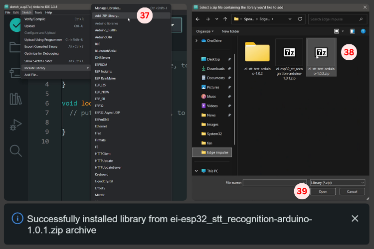
Model trained using the Edge Impulse platform, with one-click export to Arduino library for deployment on ESP32.
-
Voice interaction uses a wake word + command design: wake word “marvin”, command words “on / off” to control the LED.
-
Audio sampling rate of 16 kHz, based on I²S digital microphone capture, with simple front-end hardware.
-
Low latency, local inference, fast response, suitable for voice control of IoT devices.
-
Scalable architecture: easily add more custom wake words and commands to expand into more application scenarios.
3
Hardware Design
| Component | Quantity | Function |
| ESP32 Development Board | 1 | Main processor for offline voice recognition |
| INMP441 MEMS Microphone | 1 | High-precision audio input for ESP32 voice-to-text |
| LED (Indicator) | 1 | Visual feedback for wake word detection |
| LED (Control) | 1 | Output controlled by voice command |
| Resistors (220Ω) | 2 | LED current limiting |
| Breadboard and Jumper Wires | As needed | Prototype connections |
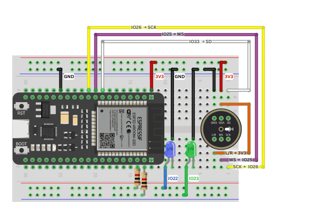
INMP441 → ESP32 Connection (Pins Used in the Project):
| INMP441 Pin | ESP32 GPIO | Signal Description |
| Left/Right | 3V3 | Channel selection (3.3V = Right channel) |
| WS (Word Select) | GPIO 25 | I²S audio left-right clock |
| SCK (Serial Clock) | GPIO 26 | Bit clock for audio data |
| SD (Serial Data) | GPIO 33 | Audio data input for ESP32 |
| VDD | 3V3 | Power supply (3.3V) |
| Ground | Ground | Ground reference |
The article also highlights a detail:
-
The default LRCLK pin used in the Edge Impulse example code is GPIO32; if you connect according to the default pins, you won’t need to modify the example code at all;
-
The schematic in this project shows GPIO25, but the author notes that you just need to synchronize the I²S configuration accordingly.
For the LED part:
-
Control LED connected to GPIO22;
-
Indicator LED connected to GPIO23;
-
Both are in series with a 220 Ω resistor for current limiting.
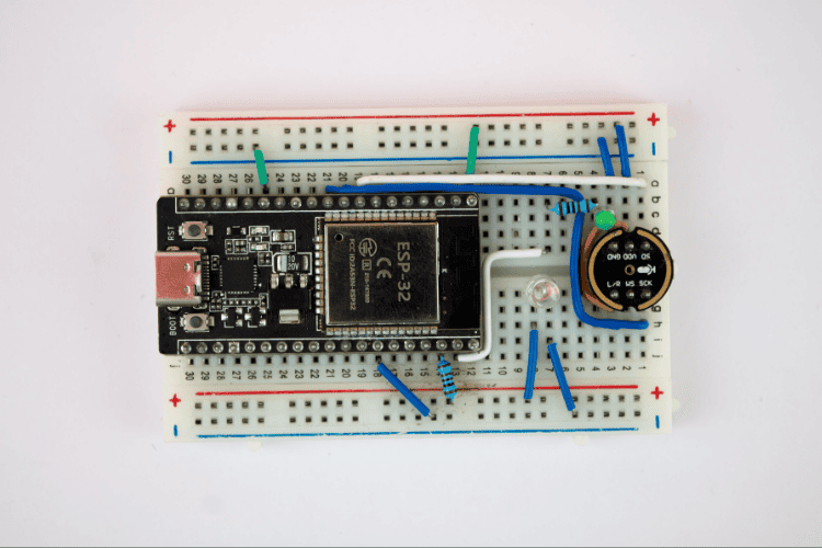
The overall wiring is minimal, making it perfect for quick prototyping on a breadboard.
4
System Architecture
From an architectural perspective, this project can be divided into three layers:
-
Data and Model Layer (PC + Edge Impulse)
-
Prepare the dataset (using Google Speech Commands V2)
-
Perform feature extraction, network training, and model evaluation on Edge Impulse
-
Finally export as an Arduino library for ESP32 to use
-
Inference and Control Layer (ESP32)
-
Run the classifier locally using the inference library generated by Edge Impulse
-
Capture I²S audio → features → inference → obtain confidence levels for each class
-
The upper state machine is responsible for the two-phase logic of “wake word + command”
-
Hardware Interaction Layer (Microphone + LED)
-
INMP441 provides a digital audio stream sampled at 16 kHz
-
One LED serves as an indicator, showing different states such as listening, waking, executing, etc.
-
Another LED acts as the controlled object, simulating an actual load (light, relay, etc.)
The overall idea is to package the AI component as much as possible into Edge Impulse, with the ESP32 only responsible for capturing, invoking, and executing, significantly reducing engineering costs.
5
Data and Model: Feeding Commands to ESP32 Using Public Datasets
The author did not record a large number of voice samples but instead chose to use established public datasets:
-
Recommended common voice datasets:
-
Google Speech Commands (keyword wake words, on/off/yes/no, etc.)
-
Mozilla Common Voice (multilingual large dataset)
-
Other voice data collections from platforms (Kaggle, Hugging Face, etc.)
-
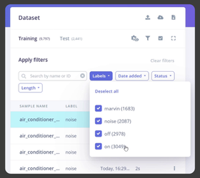
Actual usage in this project:
-
<span><span>noise</span></span>(background noise) -
<span><span>marvin</span></span>(wake word) -
<span><span>on</span></span> -
<span><span>off</span></span> -
Classes from Google Speech Commands V2: include:
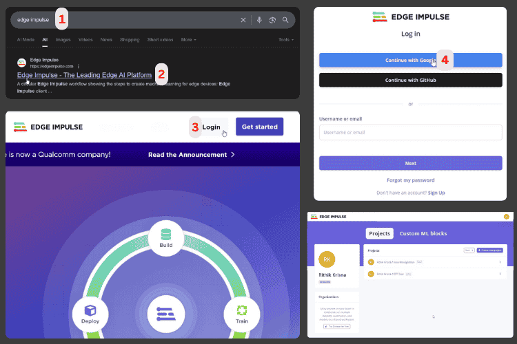
The general process in Edge Impulse:
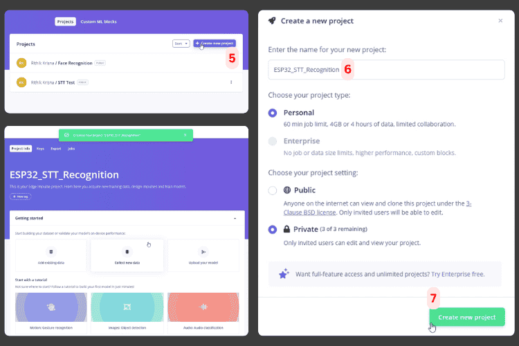
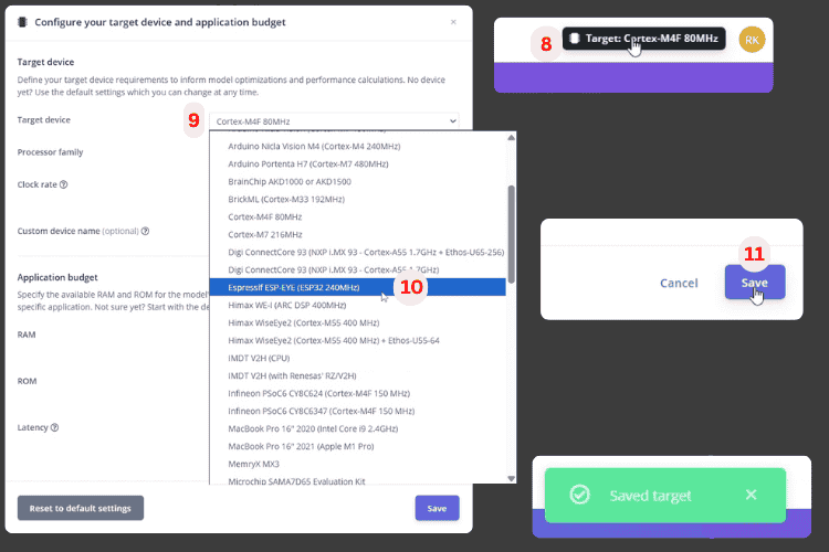
1. Register an account, create a new project, select the target device as Espressif ESP-EYE (ESP32 240 MHz) to ensure model budget fits ESP32.
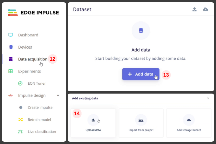
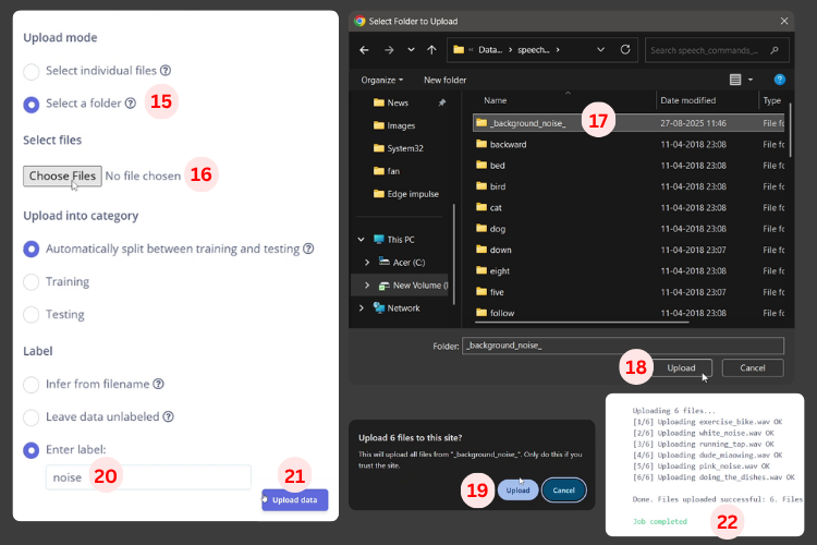
2. On the Data Acquisition page, upload the dataset, labeling folders/tags as noise, marvin, on, off.
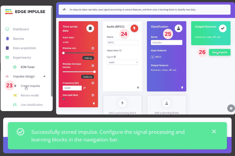
3. In Impulse Design, add audio feature extraction (e.g., MFCC) + neural network classifier.
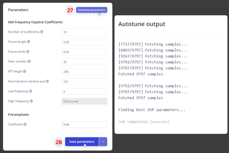
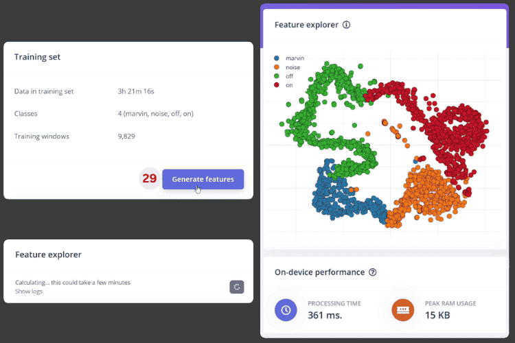
4. Use Autotune to automatically adjust feature parameters, then generate features (you can see the distribution of various classes in feature space).
5. Train the model using default network parameters, check accuracy and confusion matrix (the author believes that over 85% is sufficient for prototyping).
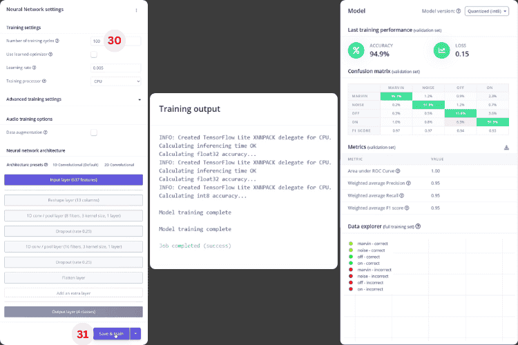
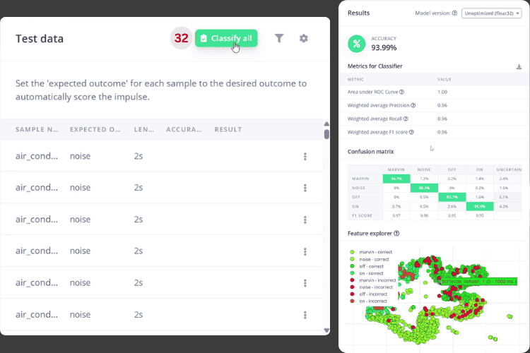
6. Use Test Model → Classify All to evaluate the performance of the test set, confirm no significant deviations, and export as an Arduino Library.

For engineers, this is equivalent to outsourcing “data + model training” to the platform, allowing them to focus on ensuring clean labels and sufficient data volume.
6
Code Structure: FreeRTOS + I²S + Edge Impulse Inference Library
On the software side, the author did not simply copy the example but created a relatively complete engineering encapsulation:
1. Key Libraries
-
Edge Impulse Inference Library:
-
For example,
<span><span>ESP32_STT_Recognition_inferencing.h</span></span>(your project name will differ) -
Encapsulates the model, feature processing, and
<span><span>run_classifier</span></span>interface -
FreeRTOS related header files:
-
Used to run background collection tasks, achieving non-blocking audio capture
-
<span><span>driver/i2s.h</span></span>: -
Configures and drives the I²S interface, responsible for communication with INMP441
2. Important Configuration and State Variables
There are several critical parameters in the code:
const float COMMAND_CONFIDENCE_THRESHOLD = 0.80; const float RECOGNITION_CONFIDENCE_THRESHOLD = 0.50;
const unsigned long LISTENING_DURATION_MS = 10000;

const int CONTROL_LED_PIN = 22;   const int INDICATOR_LED_PIN = 23;
static const uint32_t sample_buffer_size = 2048;

static bool wake_word_detected = false; static unsigned long wake_word_timestamp = 0;static bool listening_mode = false;      static bool led_state = false;         static inference_t inference;       static signed short sampleBuffer[2048];         static bool debug_nn = false;               static bool record_status = true;
Explanation of the logic:
-
0.5 confidence: used as a prompt for “what was heard”, e.g., blink the indicator light;
-
0.8 confidence: only above this will the command be executed (to prevent false triggers);
-
10-second listening window: after the wake word is triggered, the system only accepts on/off commands in the next 10 seconds;
-
A set of state variables tracks: whether it has been awakened, whether it is in listening mode, the current LED state, wake timestamp, etc.
3. Setup: Initialize Serial, LED, and Audio System
In <span><span>setup()</span></span>, the main tasks are three:
-
Open serial debugging (115200)
Serial.begin(115200);while (!Serial); // optional-
Configure the two LED pins as outputs and pull them low
pinMode(CONTROL_LED_PIN, OUTPUT);digitalWrite(CONTROL_LED_PIN, LOW);pinMode(INDICATOR_LED_PIN, OUTPUT);digitalWrite(INDICATOR_LED_PIN, LOW);-
Call
<span><span>microphone_inference_start()</span></span>: -
Allocate audio buffer
-
Initialize I²S (16 kHz sampling, DMA buffer)
-
Start background collection task
if (microphone_inference_start(EI_CLASSIFIER_RAW_SAMPLE_COUNT) == false) { ei_printf("ERR: Could not allocate audio buffer\n"); Return;}If the buffer or I²S initialization fails, an error will be printed to the serial port for easy troubleshooting.
4. Loop: Sampling → Inference → Command Processing
The main loop logic can be condensed into four steps:
-
Capture a frame of audio
bool m = microphone_inference_record();if (!m) { ei_printf("ERR: Failed to record audio...\n"); return;}-
Construct signal and call classifier
signal_t signal;signal.total_length = EI_CLASSIFIER_RAW_SAMPLE_COUNT;signal.get_data = &microphone_audio_signal_get_data;EI_IMPULSE_ERROR r = run_classifier(&signal, &result, debug_nn);-
Process recognition results according to business logic
handle_wake_word_and_commands(result);-
Print debugging information to serial
-
Print DSP and inference time
-
Print confidence levels for each label to observe model performance
ei_printf("Predictions (DSP: %d ms., Classification: %d ms.): \n", ...);for (size_t ix = 0; ix < EI_CLASSIFIER_LABEL_COUNT; ix++) { ei_printf(" %s: %.2f\n", result.classification[ix].label, ...);}5. LED “Language”: Visualizing the State Machine
The author has written a set of LED animation functions:
-
Recognizing the wake word “marvin”: the indicator LED blinks twice
-
Entering listening mode: the indicator LED stays on
-
Recognizing “on”: control the LED to turn on + indicator LED blinks to confirm
-
Recognizing “off”: control the LED to turn off + LED performs a “fade out” effect
-
Recognizing other words (but confidence does not reach 0.8): the indicator LED blinks once
-
Listening timeout: the indicator LED turns off, exiting listening mode
show_wake_word_pattern()show_listening_mode()show_turning_on_pattern()show_turning_off_pattern()show_general_recognition_pattern()stop_listening_mode()This is a highly recommended approach in embedded projects without screens—using lights to convey the state machine.
6. Audio Capture and I²S Driver
There is a dedicated set of functions responsible for audio capture:
-
The background task continuously reads audio via I²S, writing to the DMA buffer;
-
Once a frame is full, it copies the data to the inference buffer via a callback;
-
Performs necessary scaling/conversion on samples, passing them to the Edge Impulse model;
-
<span><span>i2s_init()</span></span>/<span><span>i2s_deinit()</span></span>are responsible for configuring the sampling rate (16 kHz), DMA depth, and GPIO pins.
audio_inference_callback(uint32_t n_bytes)capture_samples(void* arg)microphone_inference_start(uint32_t n_samples)microphone_inference_record(void)microphone_audio_signal_get_data(size_t offset, size_t length, float *out_ptr)microphone_inference_end(void)i2s_init(uint32_t sampling_rate)i2s_deinit(void)This part is very valuable for future reuse of “ESP32 + I²S microphone”.
7
Testing Experience: Say “marvin”, then say on/off to light up
According to the author’s description, the overall system experience is roughly as follows:
-
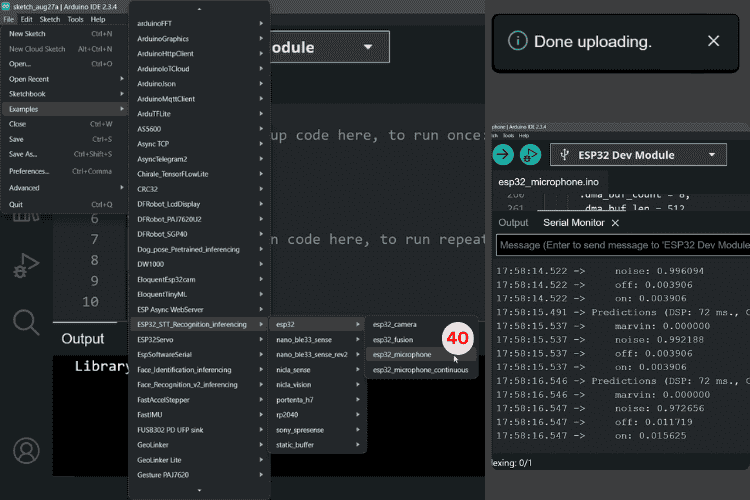
Flash the model library and project to the ESP32;
-
Open the serial monitor to see the confidence levels for each inference;
-
Say “marvin” into the microphone:
-
The indicator LED blinks twice, indicating successful recognition of the wake word;
-
The system enters a 10-second listening window (indicator LED stays on);
Then say “on”:
-
Control the LED to turn on;
-
The indicator LED blinks once to confirm;
Repeat wake + say “off”: control the LED to turn off.
Open Source Code: https://github.com/Circuit-Digest/ESP32-Voice-Control-Using-Edge-Impulse
8
Conclusion
This project is actually a complete “ESP32 Voice Recognition from 0 to 1” tutorial:
-
Upper layer uses Edge Impulse to handle data and models;
-
Middle layer uses TinyML library for real-time inference on ESP32;
-
Lower layer connects the audio stream using I²S microphone and FreeRTOS;
-
Finally, a few LEDs visualize the states and results.
If you happen to have an ESP32 and an INMP441, this project is very suitable as a “first offline voice assistant” to replicate. Start by using it to turn on lights, establish the link, and then connect the backend to the devices you truly want to control, giving your next IoT project a pair of “ears that can understand human speech”.
Note: The above content has been summarized and generated by AI. Feel free to click “Read the original” to replicate it yourself.
Click to read the original for more