Utilizing the unidirectional conductivity of diodes allows for the design of interesting and practical circuits.
This article shares an analysis of how clamping circuits and limiting circuits are implemented using diodes.
Limiting Circuit
As shown in the figure below, when in the positive half-cycle, and VIN is greater than or equal to 0.7V, the diode conducts in the forward direction. At this time, VOUT will be clamped at 0.7V.
When VIN is less than 0.7V, the diode is in the cutoff state, and during the negative half-cycle, the current reverses, and the diode is also in the cutoff state. At this time, VOUT=VIN, VOUT waveform follows the changes in VIN.
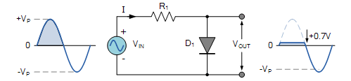
Limiting Circuit Schematic
Based on the principle of the above limiting circuit, a bidirectional limiting circuit can be designed as follows.
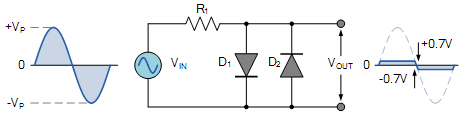
Bidirectional Limiting Circuit Schematic
However, sometimes a 0.7V voltage may not meet the requirements. So, how can we generate different levels of limiting voltage?
By adding a bias voltage VBIAS to the circuit, the diode can only conduct when VIN is greater than or equal to VBIAS. At this time, VOUT is clamped, and its value is 0.7V + VBIAS, as shown in the figure below.
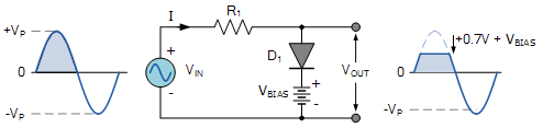
Bias Limiting Circuit Schematic
Clamping Circuit
The following is a clamping circuit realized by combining diodes with capacitors. In the analysis, the forward voltage drop of the diode is not considered, and related recommendations include: Diode Working Principle. Assuming the RC time constant is sufficiently large, so that the output waveform will not be distorted.
Clamping Circuit Principle
When the input Vin is negative during the negative half-cycle, the current flows as indicated by the red arrow in the figure below. The diode conducts, and the capacitor gradually charges to V, during which Vout=0.
When the input Vin is positive during the positive half-cycle, the current flows as indicated by the blue arrow. The diode is in the cutoff state, Vout equals the voltage across the capacitor plus the positive half-cycle voltage V, at this time Vout=2V.
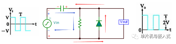
Clamping Circuit Principle
Bias Clamping Circuit
Similar to the limiting circuit, to obtain the desired clamping value, a bias voltage must be added to the circuit, as shown in the figure below.
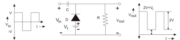
Bias Clamping Circuit
When the applied bias voltage is in the same direction as the diode conduction, the clamping value will increase to V1, Vout=2V+V1.
Example of Bidirectional Diode Clamping Circuit Application
In some circuits, the clamping effect of two diodes is used for protection, as shown in the figure below, assuming 0.7V is the conduction voltage for D1 and D2.
-
When Vin is greater than or equal to Vmax, D1 conducts, and Vout will be clamped at Vmax
-
When Vin is less than or equal to Vmin, Vout is clamped at Vmin
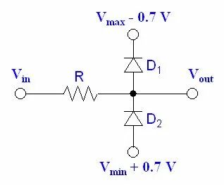
Diode Clamping Protection Circuit